Ultraviolet lamp bridging method and bridging device applying same

A technology of ultraviolet lamps and driving devices, which is applied in the manufacture of discharge tubes/lamps, machines with sequential working positions, electrical components, etc., can solve the problem of low processing efficiency and lack of good automation equipment. Batch bridge processing of ultraviolet lamps application, short switching time and other issues to achieve the effect of improving production efficiency

Pending Publication Date: 2021-01-29
佛山雪莱特照明有限公司
0 Cites 1 Cited by

AI-Extracted Technical Summary

Problems solved by technology

[0002] In the application of the ultraviolet lamp bridging process in the prior art, in order to ensure the quality of the bridging step in the application of the bridging step, manual control of the bridging process may be required, and the corresponding manual processing process has technical defects of low processing efficiency
[0003] In order to ensure t...

Abstract

The invention provides an ultraviolet lamp bridging method which comprises the following steps: S1, arranging at least two groups of lamp tubes, and arranging two groups of lamp tubes side by side; S2, preheating the two sets of lamp tubes arranged side by side; S3, respectively carrying out burn-through treatment at positions with bridging points on the two groups of preheated lamp tubes by usinga point-shaped heat source; S4, introducing inert gas into the two groups of lamp tubes subjected to burn-through treatment, so that oppositely arranged convex parts are respectively formed at bridging points of the two groups of lamp tubes; S5, enabling the bridging point positions of the two groups of lamp tubes to be subjected to tempering treatment through a planar heat source; and S6, driving the two groups of lamp tubes to move oppositely, so that the protruding parts on the two sides of the lamp tubes make contact with each other; and after contact is formed, driving the two groups oflamp tubes to move back to back, so that the convex parts on the two sides are connected to form a communicated connecting bridge. Based on the arrangement of the bridging device applying the ultraviolet lamp bridging method, the production efficiency of the ultraviolet lamp can be improved.

Application Domain

Sequential operation station machinesCold cathode manufacture

Technology Topic

EngineeringMechanical engineering +6

Image

  • Ultraviolet lamp bridging method and bridging device applying same
  • Ultraviolet lamp bridging method and bridging device applying same
  • Ultraviolet lamp bridging method and bridging device applying same

Examples

  • Experimental program(1)

Example Embodiment

[0034] In order to make the technical solution, purpose and advantages of the present invention clearer, the present invention will be further explained below in conjunction with the accompanying drawings and embodiments.
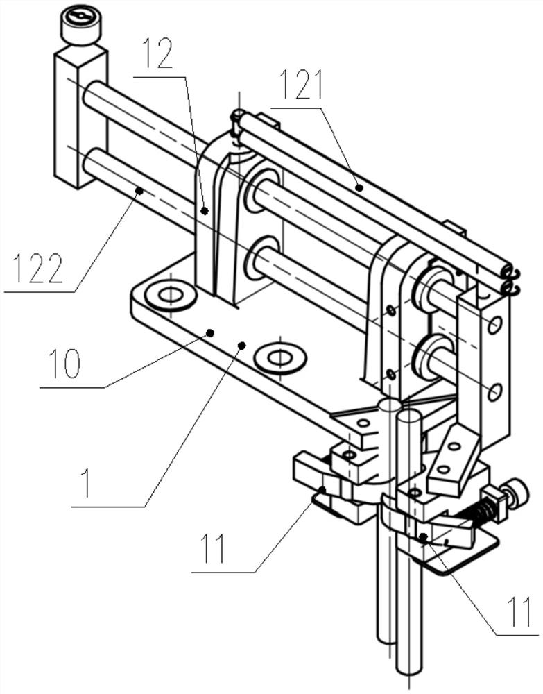
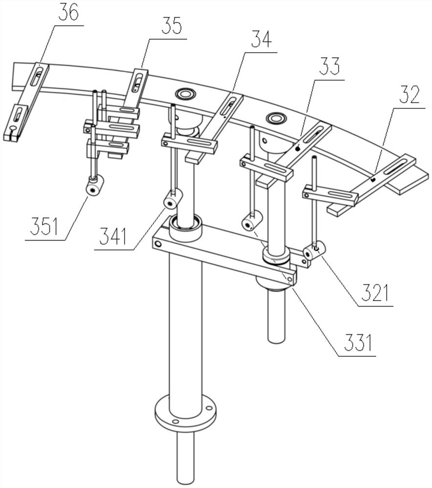
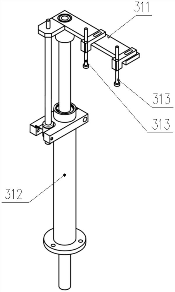
[0035] like Figure 1 to Figure 5 As shown, the bridging device is used for the bridging treatment of ultraviolet lamp tubes, and it includes a platform support 20, and a turntable mechanism is movably connected to the platform support 20, and the turntable mechanism includes a rotating platform 3, and the rotating platform 3. A plurality of working stations are arranged around the side. The rotating platform 3 is provided with a clamping part 1 for two sets of ultraviolet lamp tubes to be clamped and fixed in parallel; the rotating platform 3 is driven by a bridge drive device, The bridge drive device includes a splitter 2 linked and driven by a drive motor; driven by the bridge drive device, the rotating platform 3 drives the clamping part 1 to each of the working parts on the side. The station position makes the corresponding station switching movement.
[0036] Each of the working stations includes a flattening station 31 arranged in sequence for aligning the positions of the two groups of lamp tubes, and a station for preheating the opposing positions between the two groups of lamp tubes. Preheating station 32, blasting station 33 for burning through the lamp tubes of the two groups, ventilation station 34 for inert gas introduction of the lamp tubes for the two groups, A refiring station 35 for performing refiring treatment on one group of lamp tubes and a bridging station 36 for performing bridging treatment on two groups of said lamp tubes.
[0037] Specifically, the clamping part 1 includes a positioning bracket 10 and clamping arms 11 arranged on both sides. The clamping arms 11 on both sides are provided with a conventional spring structure, supplemented by manual attachment for The lamp tube is clamped and fixed; the clamping arm 11 on one side is positioned and attached to the positioning bracket 10; a distance adjustment mechanism 12 is arranged between the clamping arms 11 on both sides to perform the positioning on both sides. For the adjustment of the distance between the clamping arms 11, the distance adjustment mechanism 12 includes a tension spring 121 and a distance adjustment drive mechanism 122 connected to the positioning bracket 10, and the distance adjustment drive mechanism 122 can be selected and applied as an existing According to the technical cylinder drive structure, the free end of the distance-adjustable drive mechanism 122 is connected to the clamping arm 11 on the other side; one end of the tension spring 121 is connected to the positioning bracket 10, and the other end is connected to the distance-adjustable drive The free ends of the mechanism 122 are connected.
[0038] The flattening station 31 is provided with a flattening bracket 311, and the positions on both sides of the flattening bracket 311 correspond to the above-mentioned positions of the clamping arms 11 on both sides, and the flattening parts 313 on both sides are arranged. The flattening parts 313 are driven in linkage with a flattening drive mechanism 312, and the flattening drive mechanism 312 can be selected and applied as a linear drive cylinder form in the prior art; In the vertical direction, corresponding to the clamping positions of the lamp tubes of the clamping arms 11 on the lower two sides, the leveling driving action is performed on the same horizontal reference.
[0039] And on described preheating station 32, blasting station 33, ventilating station 34 and repairing fire station 35, will be respectively provided with preheating fire head device, blasting fire head device, ventilating fire head device and fire repairing fire head device , the structural form of each of the above-mentioned fire head devices is basically the same, and the fire head device is provided with an output fire head, and the output ends of the corresponding output fire heads are respectively arranged on both sides and facing away from each other.
[0040] In response to the application needs of different heating conditions of each station, the preheating fire head device includes a preheating output fire head 321, and the output flame of the preheating output fire head 321 is controlled as a preheating flame column with a temperature of 300-500 degrees Celsius.
[0041] The blasting hole burner device includes a blasting hole output burner 331, the output flame of the blasting hole output burner 331 is controlled as a blasting hole heating fire column with a temperature of 1700-1900 degrees Celsius, and the blasting hole output burner 331 controls the blasting hole heating fire column The diameter of the heating range is 3-4mm.
[0042] The ventilation fire head device includes a ventilation output fire head 341, the output flame control of the ventilation output fire head 341 is roughly the same as that of the blast hole output fire head 331, which is a ventilation heating fire column at 1700-1900 degrees Celsius.
[0043] The supplementary fire head device includes a supplementary fire output fire head 351, the output flame of the supplementary fire output fire head 351 is a supplementary fire heating column with a temperature of 1500-1600 degrees Celsius, and the supplementary fire output fire head 351 controls the heating of the supplementary fire heating column The range diameter is 6-10mm. The refueling station 35 is provided with a ventilation input device 342 for inputting inert gases such as nitrogen, and the two sides of the ventilation end of the ventilation input device 342 correspond to the positioning positions of the lamp tubes and are arranged on the refueling output burner 351 above.
[0044] The specific application principle is as follows:
[0045] Controlled according to the preset program, the flattening part 313 is made to flatten the lamp tubes on both sides, so that the preset connecting bridge position and the output fire head on each station form a horizontal alignment. Driven by the bridge drive device, the clamping part 1 drives the lamp tubes on both sides to drive and move on both sides of the output fire head on each working station respectively, then the output flame of the corresponding output fire head will be aligned with the predetermined Set the bridge position for temperature control output.
[0046] After the preheating station 32 preheats the lamp tubes on both sides with a fire source of 400 degrees Celsius, the lamp tubes on both sides are blasted with a blast hole heating fire column at 1800 degrees Celsius, so that the lamp tubes on both sides face each other The two ends facing are formed with a blasting hole for bridging treatment; then use the ventilation input device 342 to feed inert gases such as nitrogen into the lamp tube after the blasting hole, and supplemented by the heating of the ventilation heating fire column, so that the The material of the lamp tube at the part of the explosion hole protrudes under the extrusion of nitrogen gas to form a protruding part, which is used as the basis of the bridge; The protruding part is heated and softened, and the obtained blast hole can be effectively rounded, so as to better complete the preparation for the bridge. Finally, use the linear drive mechanism of the distance adjustment mechanism 12 to drive the clamping arms 11 on both sides to drive the lamp tubes close to each other, so that the softened protruding parts on both sides form a joint; and then under the action of the tension spring 121, the two sides The clamping arms 11 are separated rapidly, and so far the connecting bridges of the ultraviolet lamp tubes on both sides are formed.
[0047] Wherein, in the blast hole processing process, the flame output by the blast hole output burner 331 is a single-eyed flame core, so as to achieve the characteristics of small combustion area and concentrated firepower; , the flame output by the supplementary fire output fire head 351 is a seven-eye fire core, which has the characteristics of large combustion area and low firepower.
[0048] Then, the application of the above-mentioned bridging device can be summed up to have a kind of ultraviolet lamp bridging method, and its specific steps are applied as follows:
[0049] S1. At least two groups of lamp tubes are provided, and the lamp tubes of the two groups are arranged side by side and leveled so that the preset positions of the bridge points are aligned;
[0050] S2. Preheating the position of the bridging point between the two sets of lamp tubes arranged side by side with a heat source of 400 degrees Celsius;
[0051] S3, using a point heat source with a temperature of 1700-1900 degrees Celsius to respectively perform burn-through treatment on the two groups of lamp tubes after the preheating treatment at the position of the bridging point, the heating range of the point heat source is controlled at 3-4mm, The point heat source is the corresponding lamp tube burning through to form a blast hole with a diameter ranging from 4 to 5 mm;
[0052] S4. Introduce nitrogen gas into the two groups of lamp tubes after the burn-through treatment, and continuously heat the bridging position between the two groups of lamp tubes with a heat source in the heating range of 1700-1900 degrees Celsius; Under the pressure of nitrogen gas, so that the bridging points of the two sets of lamp tubes are respectively formed with protruding parts facing each other, and the extension size range of the protruding parts is controlled within 2-3 mm;
[0053] S5. Use a planar heat source at 1500-1600 degrees Celsius to perform supplementary fire treatment on the bridging point positions of the two groups of lamp tubes. The heating range of the planar heat source is 6-10 mm, so as to be larger than the blast hole obtained in the burn-through treatment step. diameter shall prevail;
[0054] S6. Drive the two groups of lamp tubes to move toward each other, so that the protruding parts on both sides form contact, and the contact time range is controlled within 0.7-1.3s; after the contact is formed, then drive the two groups of lamps The tube moves backwards so that the protruding parts on both sides are connected to form a connecting bridge.
[0055] In order to ensure the quality of the connecting bridge of the lamp tube of the ultraviolet lamp, the present invention will provide a design scheme of a divider 2 for performing the work station of the clamping part 1 in view of the action characteristics of the connecting process of the lamp tube. Toggles the drive application for motion.
[0056] Specifically, the divider 2 includes a roulette body 21, and a split plate 22 extends radially from the middle position on the upper side of the roulette body 21, and the split plate 22 is arranged around the roulette body 21. Including the access end 221 and the lead-out end 222, there is a separation distance 23 between the access end 221 and the lead-out end 222, and the separation distance accounts for 1/22 to 1/18 of the circumference of the roulette body 21; The partition plate 22 is provided with a straight plate-shaped access plate 24 extending away from the access end 221 at the position of the access end 221 toward the end surface of the wheel body 21 , and facing at the position of the lead end 222 . The other end surface of the roulette body 21 extends away from the lead-out end 222 with a straight plate-shaped lead-out plate 25; 40-50 degrees, and correspondingly the extension angles of the access plate 24 and the lead-out plate 25 are set to be the same; as a preferred embodiment, the extension angles of the access plate 24 and the lead-out plate 25 are both set to 45 degrees .
[0057] The central axis of the roulette body 21 is axially extended with a connecting rod to be rotatably connected to the platform support 20, and the turntable mechanism is provided with a plurality of linkage columns 202 toward the side of the roulette body 21; The turntable mechanism also includes a turntable body 201, the turntable body 201 is arranged on the upper side of the roulette body 21, the arrangement direction of the end surface of the turntable body 201 is perpendicular to the arrangement direction of the end surface of the roulette body 21, each of the The linkage columns 202 are cylindrical and are evenly distributed in the circumferential direction on the lower peripheral position of the turntable body 201. The separation pitch position to the roulette body 21 is set. The upper side of the turntable body 201 is extended with a connecting shaft at the position of its central axis and connected with the rotating platform 3 , so as to form the linkage between the divider 2 and the rotating platform 3 .
[0058] Then, under the driving of the partition driving device, the linkage posts 202 form a linkage cooperation with the peripheral side of the roulette body 21, and each linkage post 202 is connected to the corresponding partition plate 22, the access plate 24 and the lead-out plate. Under the guidance of the plate 25, it performs periodic tilting motions, thereby linking the turntable mechanism to perform self-rotating motions around its central axis.
[0059] Based on the setting of the above divider, in the application of the bridging device, the residence time of the clamping part at each station will be controlled at 5-7s, and the station switching time of the clamping part will be controlled at 1-7s. 2s.
[0060] The above is only a preferred embodiment of the present invention. For those skilled in the art, without departing from the implementation principle of the present invention, the embodiments can still be modified, and the corresponding modification schemes should also be regarded as the present invention. protection scope of the invention.

PUM

no PUM

Description & Claims & Application Information

We can also present the details of the Description, Claims and Application information to help users get a comprehensive understanding of the technical details of the patent, such as background art, summary of invention, brief description of drawings, description of embodiments, and other original content. On the other hand, users can also determine the specific scope of protection of the technology through the list of claims; as well as understand the changes in the life cycle of the technology with the presentation of the patent timeline. Login to view more.

Similar technology patents

Precise extrusion molding method of thin wall long-pipe shaped parts bland and special mould

InactiveCN101332476AIncreased dimensional accuracy and material utilizationIncrease productivity
Owner:HENAN UNIV OF SCI & TECH

UV-curable colored paint composition

Owner:JIANGSU KUANGSHUN PHOTOSENSITIVITY NEW MATERIAL

Classification and recommendation of technical efficacy words

Why Eureka
Try Eureka