Lithium battery pack case for communication base station

A technology for a lithium battery pack and a communication base station is applied in the field of lithium battery pack chassis, which can solve the problems of lower cooling efficiency of the chassis and unsmooth air intake, and achieve the effects of smooth air intake and efficient heat dissipation.

Active Publication Date: 2021-01-29
湖北鸿兴时代新能源科技有限公司
View PDF5 Cites 2 Cited by
  • Summary
  • Abstract
  • Description
  • Claims
  • Application Information

AI Technical Summary

Problems solved by technology

[0003] The purpose of the present invention is to solve the disadvantages in the prior art that the air intake is not smooth after the filter screen on the air inlet is blocked, so that the heat dissipation efficiency of the chassis is reduced, and a lithium battery pack chassis for communication base stations is proposed.

Method used


Image

  • Lithium battery pack case for communication base station
  • Lithium battery pack case for communication base station
  • Lithium battery pack case for communication base station

Examples


Embodiment 1

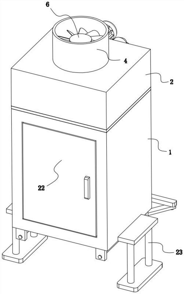
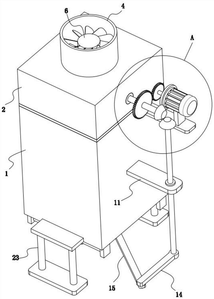
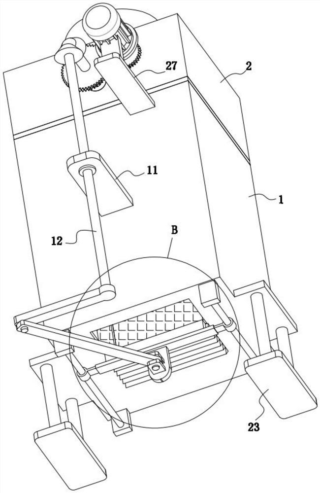
[0022] refer to Figure 1-8 , a lithium battery case for a communication base station, comprising a first box body 1, a dodge door 22 is hingedly mounted on the first box body 1, and two corresponding supporting legs are fixedly installed on the lower part of the outer wall of the first box body 1 23. The top of the first box body 1 is fixedly installed with the second box body 2 communicating with it inside, a filter grid 3 is arranged between the first box body 1 and the second box body 2, and the top surface of the second box body 2 is fixed A cylinder 4 communicating with it is installed inside, and a first rotating shaft 5 coaxially arranged with it is rotatably installed in the cylinder 4, and a fan blade 6 is fixedly installed on the top of the first rotating shaft 5, and on the outer wall of the first box body 1 A fixed plate 11 is fixedly installed, and a third rotating shaft 12 parallel to the first rotating shaft 5 is rotatably installed on the fixing plate 11. The ...

Embodiment 2

[0028] refer to Figure 1-8 , as another preferred embodiment of the present invention, the difference from Embodiment 1 is that a scraper 21 corresponding to the movement track of the brush 17 is provided on one side of the filter screen 18, and the scraper 21 is fixedly installed on the first box 2 On the bottom surface, the scraper 21 is formed by a number of triangular prisms arranged at equal intervals, and the triangular prisms are all set towards the side away from the second rotating shaft 12 .

[0029] When the crank-link mechanism drives the brush 17 to reciprocate in a straight line along the guide rod 19, when the brush 17 passes the scraper 21, the triangular prism on the scraper 21 will scrape off the impurities attached to the bristles of the brush 17, In this way, it is avoided that too many impurities are attached to the brush 17 and the cleaning effect is deteriorated.


PUM


Abstract

The invention relates to the technical field of battery pack cases, and particularly relates to a lithium battery pack case for a communication base station. Fan blades are fixedly mounted at the topend of a first rotating shaft, a fixing plate is fixedly mounted on the outer wall of a first case body, and a third rotating shaft parallel to the first rotating shaft is rotatably mounted on the fixing plate; the third rotating shaft and the first rotating shaft are in transmission connection to the same driving module, the bottom end of the third rotating shaft extends downwards to the positionbelow the first case body, two parallel guide rods are fixedly installed on the lower surface of the first case body, the two guide rods are each provided with a rod sleeve, and a brush is fixedly installed between the two rod sleeves; and an air inlet is formed in the bottom of the first case body, a filter screen is installed on the air inlet, and the brush is in transmission connection with the third rotating shaft through a crank connecting link mechanism. By arranging the crank connecting link mechanism and the brush, the filter screen on the air inlet can be cleaned in real time so thatheat dissipation of the case can be efficiently carried out.

Description

technical field [0001] The invention relates to the technical field of a battery box, in particular to a lithium battery box used for a communication base station. Background technique [0002] Communication base stations located outdoors generally need to be equipped with a lithium battery pack for power supply, and the lithium battery pack needs to be installed in a dedicated chassis. During the power supply process of the lithium battery, it will generate a lot of heat. In order to ensure the normal operation of the lithium battery, it is necessary to install a cooling fan and other mechanisms in the chassis. Some communication base stations in remote outdoor areas will enter the air in the computer room. Dust , mosquitoes and other impurities, and after the cooling fan is installed, when the cooling fan is running, the external air will be sent into the box, and the hot air inside the box will be discharged. At this time, the dust and mosquitoes in the computer room will...

Claims


Application Information

Patent Timeline
IPC IPC(8): H01M50/251H01M10/613H01M10/627H01M10/6563B01D46/00B01D46/10
CPCH01M10/613H01M10/627H01M10/6563B01D46/10B01D46/681Y02E60/10
Inventor 黎标金璇陈兴奎
Owner 湖北鸿兴时代新能源科技有限公司
Why Eureka
Try Eureka