Single-output-shaft liquid ring type vacuum pump internally provided with sliding bearing

A technology of liquid ring vacuum pump and sliding bearing, which is applied in the direction of rotary piston type/oscillating piston type pump components, rotary piston type pumps, parts of pumping devices for elastic fluid, etc., which can solve the problem of sealing performance and safety and reliability Poor performance, inconvenient installation and maintenance, large floor space, etc., to improve the sealing effect, save raw materials, and reduce weight

Inactive Publication Date: 2018-09-28
山东精工泵业有限公司
View PDF0 Cites 0 Cited by
  • Summary
  • Abstract
  • Description
  • Claims
  • Application Information

AI Technical Summary

Problems solved by technology

[0004] 1. Equipment with high energy consumption and low efficiency. The existing double-shaft liquid ring vacuum pump consumes a lot of raw materials, has poor sealing performance, safety and reliability, and low cost performance
[0005] 2. It occupies a large area and is inconvenient for installation and maintenance

Method used


Image

  • Single-output-shaft liquid ring type vacuum pump internally provided with sliding bearing
  • Single-output-shaft liquid ring type vacuum pump internally provided with sliding bearing
  • Single-output-shaft liquid ring type vacuum pump internally provided with sliding bearing

Examples


Embodiment 1

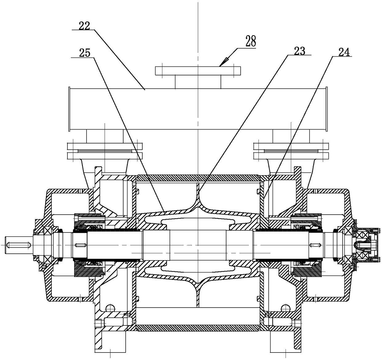
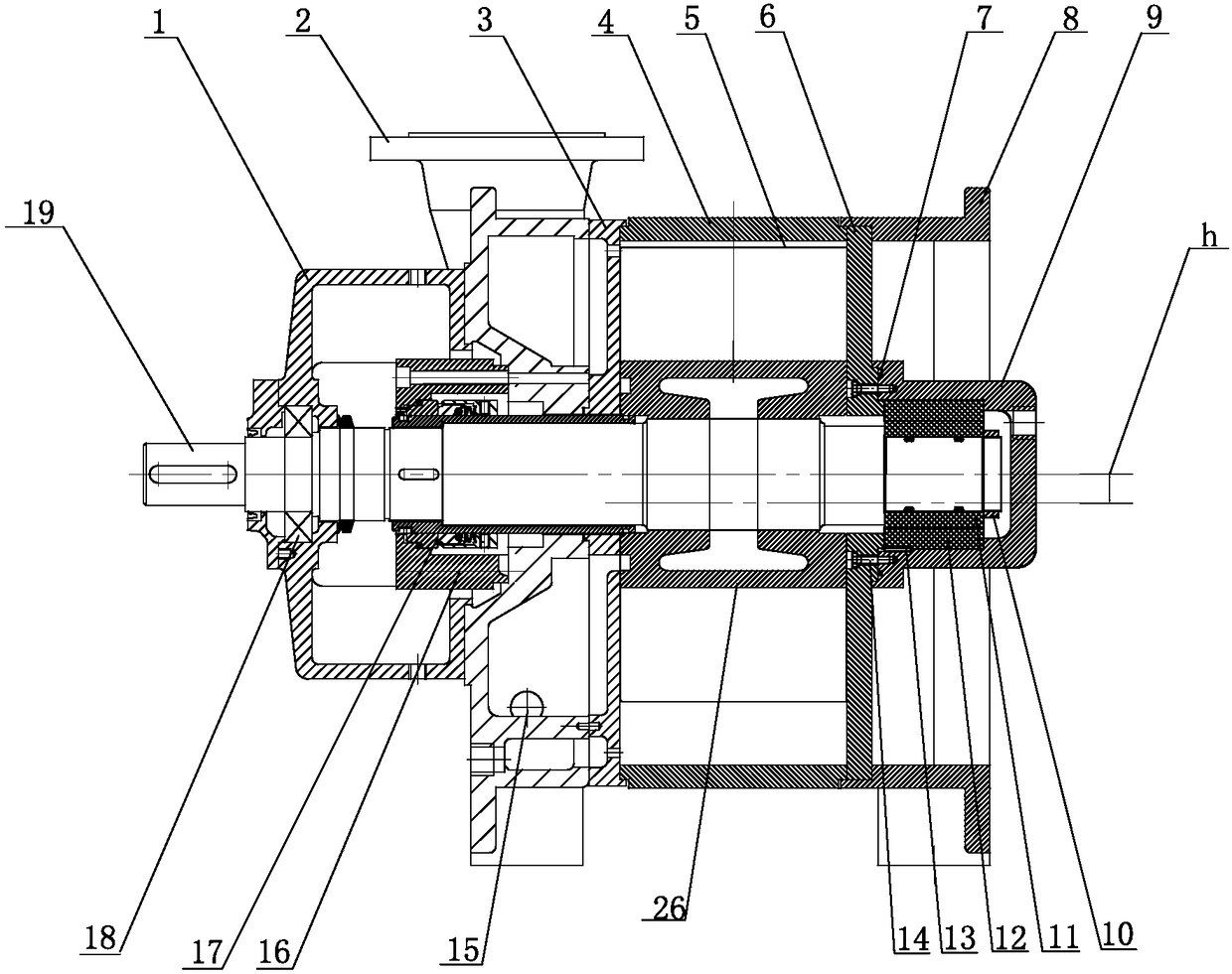
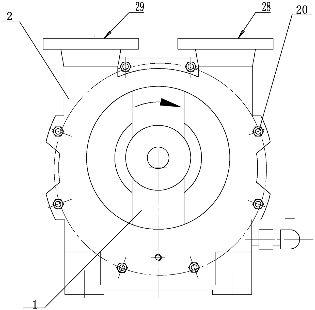
[0037] Such as Figure 1 to Figure 5 As shown, the single-outlet shaft liquid ring vacuum pump with built-in sliding bearings according to the present invention includes a pump body 4, a pump shaft 19 is provided through the pump body 4, and a distribution plate 3, a second A pump cover 2, a mechanical seal seat 16 and an external bearing seat 1, the first end of the pump shaft 19 runs through the distribution plate 3, the first pump cover 2, the mechanical seal seat 16 and the external bearing seat 1, and the second end of the pump shaft 19 The end is installed in a sliding bearing seat 9 with one end closed, and a second pump cover 8 is provided outside the sliding bearing seat 9, and a sealing cover 6 is provided between the second pump cover 8 and the pump body 4, and the pump shaft 19 runs through the sealing cover 6 set up. A liquid inlet is arranged on the first pump cover. The pump shaft 19 is connected to the outer bearing seat 1 through the rolling bearing 18, and ...

Embodiment 2

[0041] Such as Figure 1 to Figure 5 As shown, on the basis of Example 1, the sliding bearing outer sleeve 12 is a pressureless sintered ceramic sliding bearing outer sleeve; the sliding bearing inner sleeve 11 is a pressureless sintered ceramic sliding bearing inner sleeve. The sliding bearing outer sleeve 12 is fixedly connected to the sliding bearing seat 9 through positioning pins 13 ; the sliding bearing inner sleeve 11 is fixedly connected to the pump shaft 19 through a round nut 10 .

Embodiment 3

[0043] Such as Figure 1 to Figure 5As shown, on the basis of Embodiment 2, the impeller 5 is arranged on the pump shaft 19 in the pump body 4, and the impeller 5 includes a straight cylindrical impeller hub 26 arranged on the pump shaft. The gap between the impeller 5 and the distribution disc 3 is 0.3-0.5mm. The gap between the impeller 5 and the sealing cover 6 is 0.3-0.5mm. There is an eccentricity h between the impeller and the pump body. The eccentricity h can be set according to conventional technology.


PUM


Abstract

The invention relates to a single-output-shaft liquid ring type vacuum pump internally provided with a sliding bearing, and belongs to the technical field of vacuum obtaining equipment. The single-output-shaft liquid ring type vacuum pump comprises a pump body, a pump shaft penetrates the pump body, and the first end of the pump body is sequentially provided with a distribution disc, a first pumpcover, a mechanical seal base and an outer bearing block. The first end of the pump shaft penetrates the distribution disc, the first pump cover, the mechanical seal base and the outer bearing block.The second end of the pump shaft penetrates a sliding bearing block with one end closed. A second pump cover is arranged at the outer portion of the sliding bearing block, and a seal cover is arrangedbetween the second pump cover and the pump body. The pump shaft penetrates the seal cover. The single-output-shaft liquid ring type vacuum pump is simple in structure, few raw materials are consumed,the manufacturing cost is low, the occupied area is small, the sealing performance is good, running is safe and reliable, and installing and maintaining are convenient.

Description

technical field [0001] The invention relates to a single-shaft liquid ring vacuum pump with a built-in sliding bearing, which belongs to the technical field of vacuum obtaining equipment. Background technique [0002] The liquid ring vacuum pump is the equipment with the largest pumping capacity and the most widely used rough vacuum. It can also be used as a compressor. When used as a compressor, it is called a liquid ring compressor. Since the gas compression process of the liquid ring vacuum pump is basically isothermal, it can pump flammable and explosive gases, and it can also pump dust-containing and water-containing gases. Because of its above-mentioned characteristics, therefore, In many industries such as chemical industry, pharmaceutical, metallurgy, coal, petroleum, electric power, etc., the application of liquid ring vacuum pump is increasing day by day. Such as figure 1 As shown, the liquid ring vacuum pump includes a pump body 4, a pump shaft 19 is arranged in...

Claims


Application Information

Patent Timeline
Patent Type & Authority Applications(China)
IPC IPC(8): F04C19/00F04C25/02F04C27/00F04C29/00
CPCF04C19/00F04C25/02F04C27/001F04C29/00F04C2240/30F04C2240/51
Inventor 李峰李娟孙继杰商玉玲李彪
Owner 山东精工泵业有限公司
Why Eureka
Try Eureka