Grooving equipment for mold production

A mold and equipment technology, applied in the field of slotting equipment for mold production, can solve problems such as errors

Inactive Publication Date: 2021-02-02
刘传福
View PDF0 Cites 0 Cited by
  • Summary
  • Abstract
  • Description
  • Claims
  • Application Information

AI Technical Summary

Problems solved by technology

[0004] In order to overcome the shortcomings of the existing mold grooving technology that is prone to errors, the invention provides a grooving equipment for mold production that improves the grooving accuracy of the production mold

Method used


Image

  • Grooving equipment for mold production
  • Grooving equipment for mold production
  • Grooving equipment for mold production

Examples


Embodiment 1

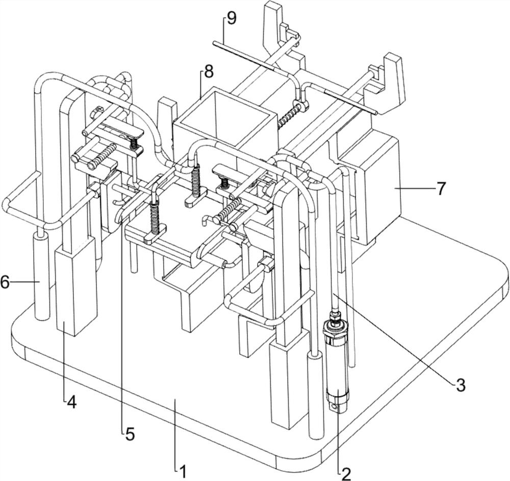
[0024] A slotting equipment for mold production, such as figure 1 As shown, it includes a base plate 1, a cylinder 2, a push rod 3, a slotting mechanism 4 and an alignment mechanism 5. A cylinder 2 is installed on the right side of the upper front of the base plate 1, and a push rod 3 is connected to the top of the cylinder 2. The upper front portion of the base plate 1 A slotting mechanism 4 is provided, and the slotting mechanism 4 is connected with the push rod 3 , and an alignment mechanism 5 is provided on the upper part of the slotting mechanism 4 .

[0025] When people need to slot a production mold, they can use this slotting equipment. First, people put the mold on the alignment mechanism 5, and then open the cylinder 2, which drives the push rod 3 to move downward, thereby driving the slotting Mechanism 4 slots the mold, and the operation of slotting mechanism 4 drives the alignment mechanism 5 to clamp and fix the mold so that it is aligned left and right when slott...

Embodiment 2

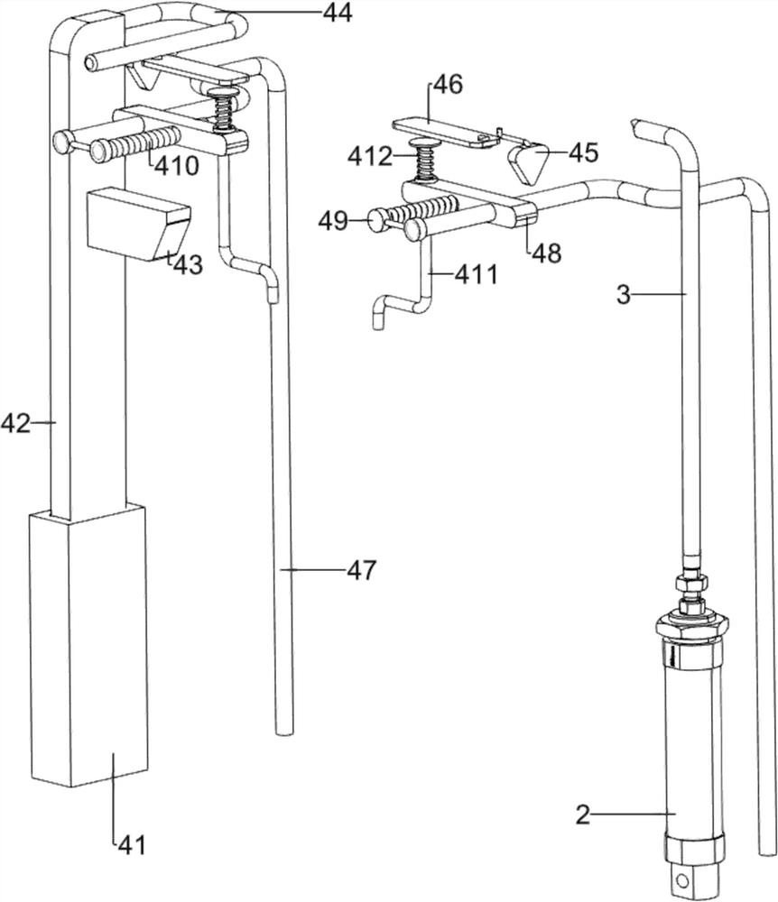
[0027] On the basis of Example 1, such as figure 2 , image 3 and Figure 4 As shown, the slotting mechanism 4 includes a first sleeve 41, a telescopic rod 42, a projection 43, a pressing contact rod 44, a triangular block 45, an elongated square plate 46, a first pole 47, a sliding block 48, a fixed Tool 49, the first spring 410, the scratching knife 411 and the second spring 412, the left and right sides of the upper front part of the bottom plate 1 are all provided with the first sleeve 41, and the two first sleeves 41 tops are all provided with telescopic rods 42, both The inner side of the top telescopic rod 42 is symmetrically provided with a projection 43, and the rear wall of the top of the two telescopic rods 42 is symmetrically provided with a pressing contact rod 44, and the pressing contact rod 44 on the right side is connected with the push rod 3, and the two pressing contact rods 44 front outsides are all provided with triangular block 45, and two downward con...

Embodiment 3

[0032]On the basis of Example 2, such as figure 1 , Figure 5 and Figure 6 As shown, it also includes a pressing mechanism 6. The upper front part of the bottom plate 1 is provided with a pressing mechanism 6. The pressing mechanism 6 includes a second sleeve 61, a first connecting rod 62, a second telescopic frame 63, and a pressure frame assembly. 64 and the fourth spring 65, the left and right sides of the upper front part of the bottom plate 1 are provided with second sleeves 61, and the second telescopic frame 63 is connected between the two second sleeves 61, and the left and right sides of the second telescopic frame 63 middle part The first connecting rods 62 are arranged symmetrically, and the two first connecting rods 62 are matched with the protruding blocks 43 that are close together. A pressure frame assembly 64 is arranged in the middle of the upper part of the second telescopic frame 63, and two first connecting rods are wound around the pressure frame assembl...


PUM


Abstract

The invention relates to grooving equipment, in particular to grooving equipment for mold production. The grooving equipment for mold production improves the grooving precision of a production mold. The grooving equipment for mold production comprises: a bottom plate, provided with an air cylinder; a pushing rod, connected with the top of the air cylinder; a grooving mechanism, arranged on the side, close to the air cylinder, of the bottom plate, and connected with the push rod; and an aligning mechanism, arranged at the upper portion of the grooving mechanism. According to the grooving equipment, convex blocks move downwards to be in contact fit with rectangular blocks, so that the rectangular blocks move inwards, first connecting columns slide inwards, alignment blocks move inwards, andthe effect of extruding and fixing molds above a table block to enable the molds to be aligned left and right is achieved.

Description

technical field [0001] The invention relates to a slotting device, in particular to a slotting device for mold production. Background technique [0002] Mold refers to various molds and tools used in industrial production for injection molding, blow molding, extrusion, die-casting or forging forming, smelting, stamping and other methods to obtain the required products. In short, molds are tools used to shape objects , has the title of "mother of industry", the mold often needs to be grooved on the mold body during the processing process, but the current mold groove equipment is easy to move the mold body during the groove operation, so it is easy to appear Errors affect the processing quality. [0003] In order to enhance the grooving effect of the production mould, it is necessary for us to design a grooving device that can accurately align and compact the mould, aiming at the shortcomings of the existing technology. Contents of the invention [0004] In order to overco...

Claims


Application Information

Patent Timeline
Patent Type & Authority Applications(China)
IPC IPC(8): B23D79/00B23Q3/08
CPCB23D79/00B23Q3/08
Inventor 刘传福
Owner 刘传福
Why Eureka
Try Eureka