
Lifting device for parts disengaging from positioning pins

A technology for positioning pins and parts is applied in the field of lifting devices for parts disengaging positioning pins, which can solve the problems of inability to achieve vertical lifting, high labor intensity, and scrapping of parts, and achieves simple structure, stable and reliable lifting and lowering, and convenient operation. Effect

Active Publication Date: 2021-02-02
东风汽车底盘系统有限公司
View PDF8 Cites 0 Cited by
  • Summary
  • Abstract
  • Description
  • Claims
  • Application Information

AI Technical Summary

Problems solved by technology

However, the above method has the following shortcomings: the weight of the part is 15-25Kg, limited by the machine tool conditions, the horizontal machining center has a side door, and the top of the workbench is semi-closed, and the lifting center of the part is not at the center of the workbench, so vertical lifting cannot be realized. Lifting at an angle that is too small, there is a skewed lifting, and it is very easy to damage the pin holes that have been finished, resulting in the scrapping of parts. The matching gap between the positioning hole and the positioning hole is 0.004 ~ 0.014mm, and the depth matching length is 8 ~ 13mm
In order to avoid parts being scrapped, the parts can only be lifted by manual hands, because it is mass-produced, so the labor intensity of the workers is very high
Therefore, it is necessary to design a lifting device on the manual tooling. However, the height of the bottom plate of the manual fixture and the positioning block is only 52mm, and the space is very small. It is necessary to design a lifting device that meets the requirements within a narrow range.

Method used


Image

  • Lifting device for parts disengaging from positioning pins
  • Lifting device for parts disengaging from positioning pins
  • Lifting device for parts disengaging from positioning pins

Examples


Embodiment Construction

[0031] The present invention will be further described in detail below in conjunction with specific examples to facilitate a clear understanding of the present invention, but they do not limit the present invention.

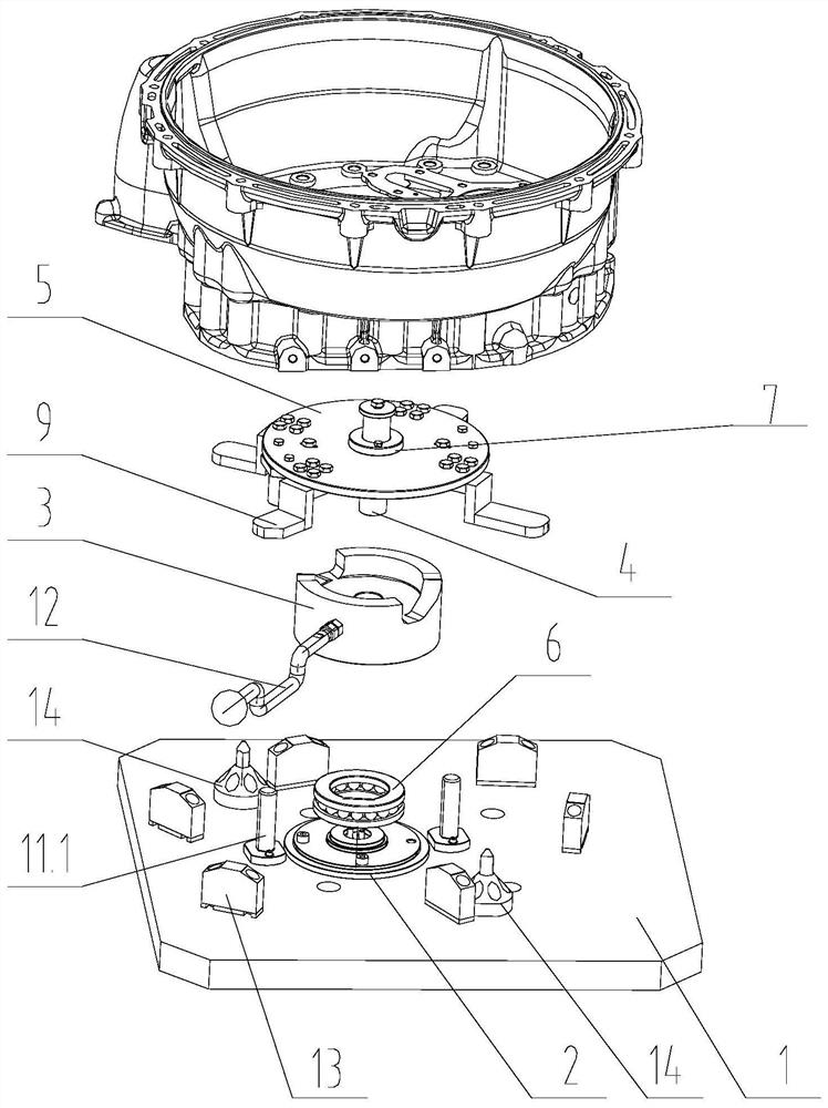
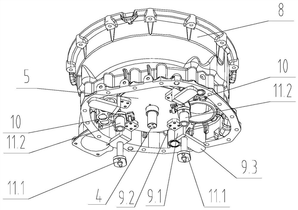
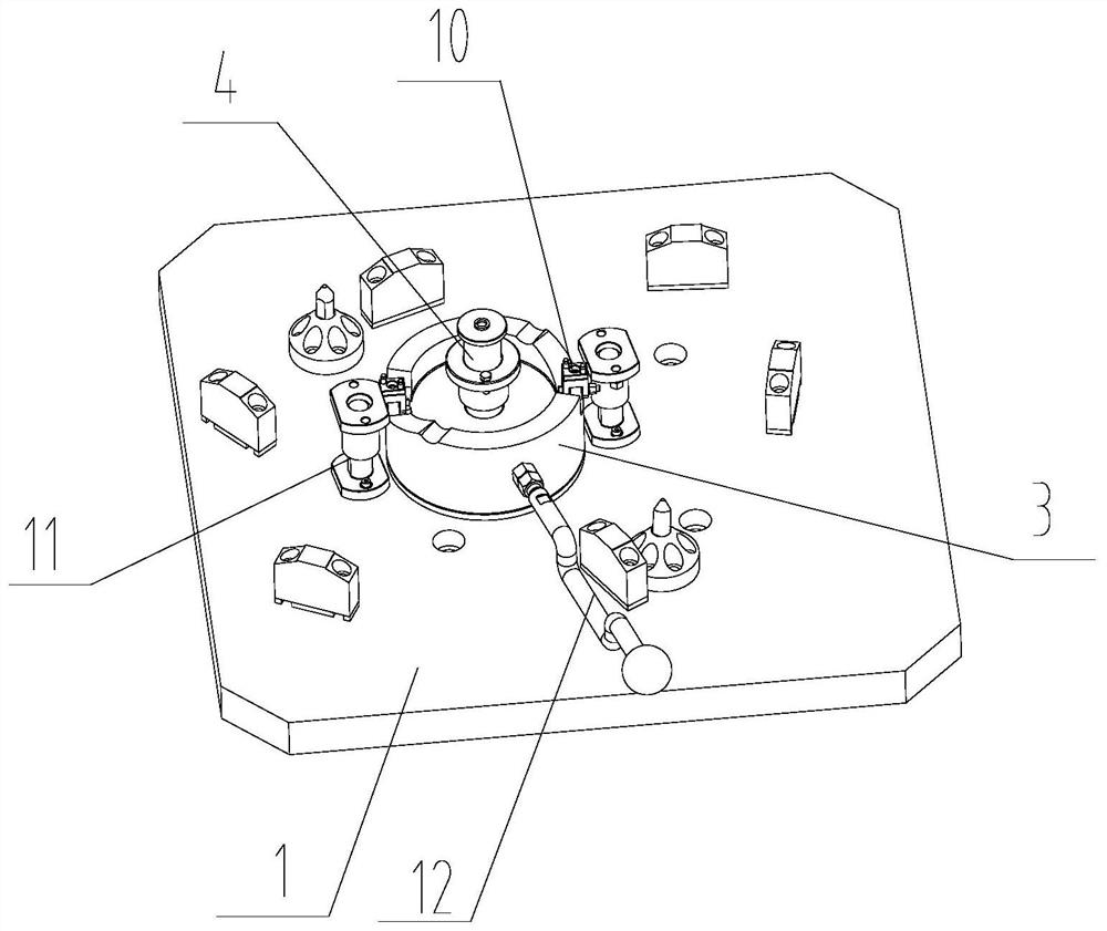
[0032] like figure 1 A lifting device for disengaging positioning pins is shown, which is characterized in that it includes a fixture bottom plate 1, a base 2 set on the fixture bottom plate 1, an end cam 3 set on the base 2, and a middle part of the end cam 3. Upright 4, the top of described end face cam 3 is provided with connecting plate 5, between described end face cam 3 and base 2 is connected by bearing 6 rotation; The bottom end of described upright 4 is fixedly connected with base 2, and The top runs through the connecting plate 5, and a bushing 7 is arranged between the middle part of the column 4 and the connecting plate 5, and several lifting plates 9 for lifting or lowering parts 8 are arranged around the connecting plate 5; Several driven wheel mec...


PUM


Abstract

The invention discloses a lifting device for parts disengaging from positioning pins. The lifting device comprises a clamp bottom plate, a base arranged on the clamp bottom plate, an end face cam arranged on the base and a stand column arranged in the middle of the end face cam. A connecting plate is arranged at the top end of the end face cam, and the end face cam is rotationally connected with the base through a bearing. Multiple lifting plates for lifting or dropping the parts are arranged around a connecting plate. Multiple driven wheel mechanisms are arranged below the connecting plate. Multiple lifting grooves and falling grooves are formed in the top end face of the end face cam, the lifting grooves and the falling grooves are in transition connection through sliding faces, and theend face cam can rotate around the stand column under the action of external force so that the driven wheel mechanisms can move along the sliding faces of the end face cam to lift or drop the parts. The lifting device for the parts disengaging from the positioning pins is simple in structure, convenient to operate and capable of lifting or dropping the parts in a narrow space.

Description

technical field [0001] The invention belongs to the technical field of transmission case parts, and in particular relates to a device for lifting a part from a positioning pin. Background technique [0002] At present, for the front case / rear case of the fourteen-speed gearbox case, manual clamps are used to process side holes on horizontal machining. However, the above method has the following shortcomings: the weight of the part is 15-25Kg, limited by the machine tool conditions, the horizontal machining center has a side door, and the top of the workbench is semi-closed, and the lifting center of the part is not at the center of the workbench, so vertical lifting cannot be realized. Lifting at an angle that is too small, there is a crooked pull, and it is very easy to damage the pin holes that have been finished, resulting in scrapped parts. The matching gap between the positioning hole and the positioning hole is 0.004-0.014mm, and the depth matching length is 8-13mm. I...

Claims


Application Information

Patent Timeline
Patent Type & Authority Applications(China)
IPC IPC(8): B25B27/02
CPCB25B27/02
Inventor 朱仕海吴红建熊亘王海华
Owner 东风汽车底盘系统有限公司
Learn More