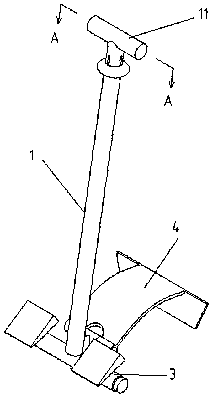
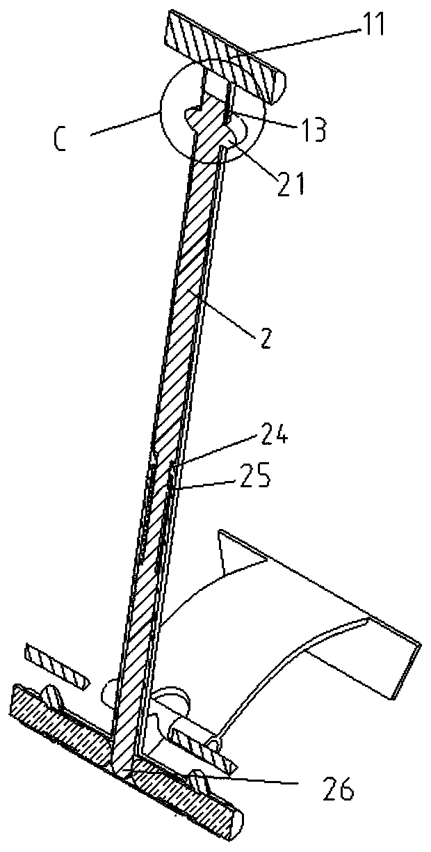
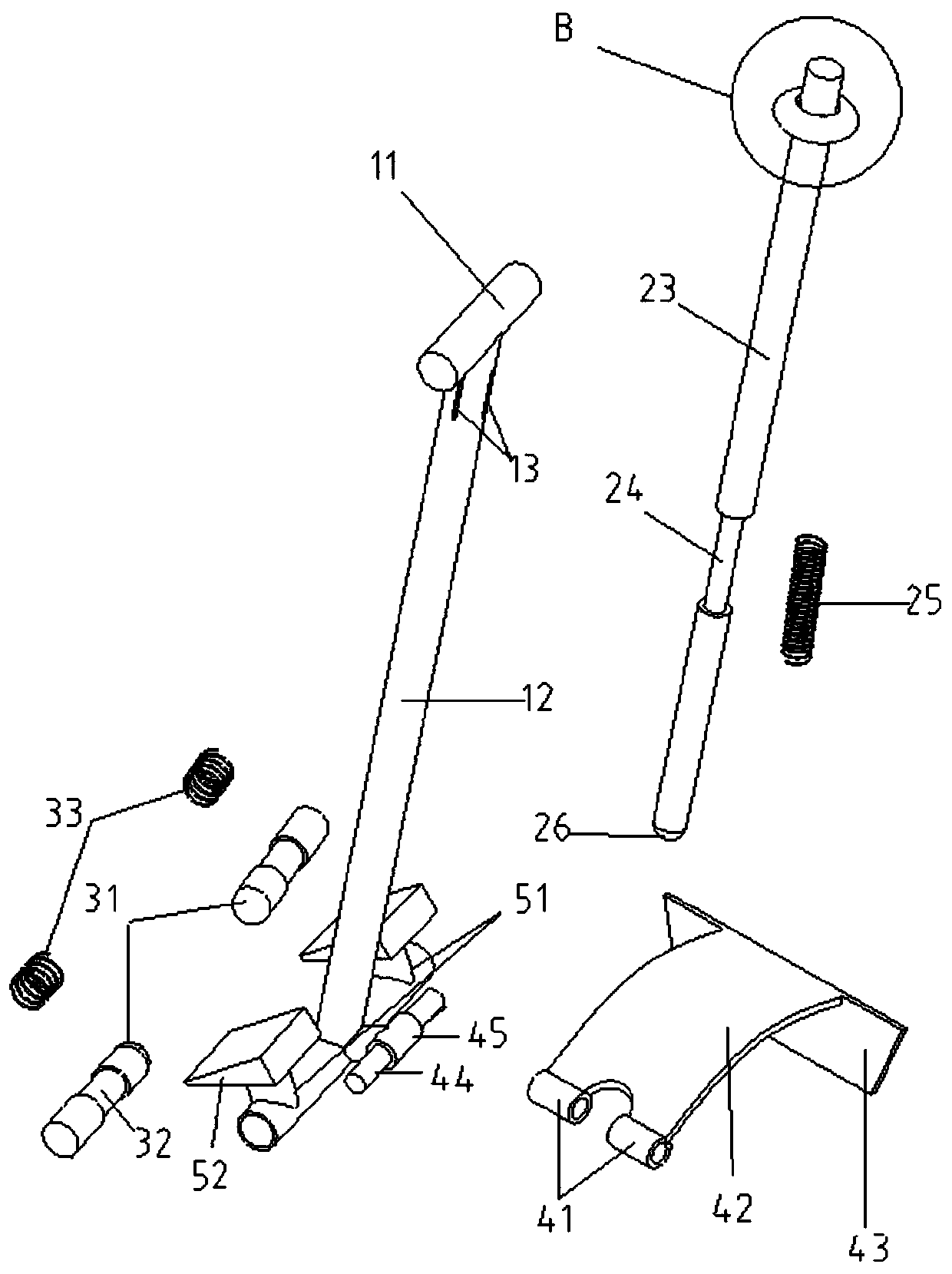
C-shaped steel lifting device

A C-shaped steel and lifter technology, which is applied to hand-held tools, manufacturing tools, etc., can solve the problems of C-shaped steel movement, difficulty in lifting, etc., and achieve the effects of simple structure, avoiding safety accidents, and facilitating safety.

Pending Publication Date: 2020-01-21
LIHUAYI LIJIN REFINING & CHEMICAL CO LTD
View PDF0 Cites 0 Cited by
  • Summary
  • Abstract
  • Description
  • Claims
  • Application Information

AI Technical Summary

Problems solved by technology

[0004] In order to solve the technical problem of difficult movement and pulling of C-shaped steel in the prior art, the present invention provides a C-shaped steel puller

Method used


Image

  • C-shaped steel lifting device
  • C-shaped steel lifting device
  • C-shaped steel lifting device

Examples


Embodiment Construction

[0020] The invention discloses a C-shaped steel pulling device, and those skilled in the art can learn from the content of this article, and appropriately improve parts and components can be realized. In particular, it should be pointed out that all similar substitutions and modifications are obvious to those skilled in the art, and they are all considered to be included in the present invention. The method and application of the present invention have been described through the preferred embodiments. It is obvious that relevant persons can modify or appropriately change and combine the methods and applications described herein without departing from the content, spirit and scope of the present invention to achieve and Apply the technology of the present invention.

[0021] In order to enable those skilled in the art to better understand the present invention, the present invention will be further described in detail below in conjunction with specific embodiments.

[0022] The pre...


PUM


Abstract

The invention relates to the technical field of lifting devices, and discloses a C-shaped steel lifting device. The lifting device comprises a main rod, an auxiliary rod and a protruding rod, whereinthe main rod comprises a handle and a hollow vertical rod which are of an integrated structure; a plurality of sections of sliding ways are formed in the position, close to the handle, of the verticalrod along the circumference of the vertical rod; a first limiting protrusion is arranged on the inner wall of the middle of the vertical rod; the auxiliary rod is mounted in the hollow vertical rod;the auxiliary rod is provided with a plurality of connecting pieces; the connecting pieces penetrate out of the sliding ways; linkage hand rings are arranged at the tail ends of the connecting pieces;the linkage hand rings can pull the auxiliary rod to slide along the sliding ways through the connecting pieces; the auxiliary rod is provided with a first groove corresponding to the first limitingprotrusion in position; a first reset spring is mounted in the first groove; a circular push head is arranged at the tail end of the auxiliary rod; the protruding rod and the hollow vertical rod are integrally arranged; the protruding rod is a hollow protruding rod; two telescopic rods are mounted in the hollow protruding rod; second grooves are formed in the middle positions of the telescopic rods; and second reset springs are mounted in the second grooves. The lifting device is simple in structure, high in working efficiency and capable of avoiding safety accidents.

Description

Technical field [0001] The invention relates to a pulling device, in particular to a C-shaped steel pulling device. Background technique [0002] C-shaped steel is widely used in the purlins, wall beams, roof trusses, brackets of steel structure buildings. In addition, it can also be used in columns, beams and arms in mechanical light industry manufacturing. Workers need to move the C-shaped steel frequently during the construction process. Because the C-shaped steel itself is relatively heavy and has sharp corners, it is difficult to move, people are sprained or scratched, and other equipment is damaged. So far, there is no effective measure to solve such problems. [0003] In order to overcome the above-mentioned drawbacks of the prior art, the present invention provides a C-shaped steel pulling device that is safe and portable, and can realize easy lifting and moving, hoisting and other operations of the C-shaped steel. Summary of the invention [0004] In order to solve the te...

Claims


Application Information

Patent Timeline
Patent Type & Authority Applications(China)
IPC IPC(8): B25B9/00
CPCB25B9/00
Inventor 王春凯李安训尹峰峰
Owner LIHUAYI LIJIN REFINING & CHEMICAL CO LTD
Why Eureka
Try Eureka