Construction method of gas injection hole

A construction method and air injection hole technology, which is applied to drilling equipment and methods, earthwork drilling, mining fluids, etc., can solve problems such as low mining efficiency, low water supply, and high cost of brine mining, so as to improve mining efficiency and reduce mining costs. Halogen cost, effect of enhanced oil recovery

Active Publication Date: 2021-02-02
青海凹口凸钾镁盐技术有限公司
View PDF10 Cites 0 Cited by
  • Summary
  • Abstract
  • Description
  • Claims
  • Application Information

AI Technical Summary

Problems solved by technology

Through high-intensity mining in recent decades, some salt lakes have no brine to be recovered, and most of the subsurface brine mines in the salt rock formations of the salt lakes have been exhausted, especially the salt lakes in the Qaidam Basin. Salt lakes have temporarily alleviated the plight of brine mining through water replenishment and solid-liquid conversion, and the brine mining volume of most of the salt lakes can no longer meet production needs
[0003] In the salt lake area of ​​the Qaidam Basin, there is a large amount of deep brine below the surface salt rock layer. Due to the deep burial of the strata, the formation time of the deep brine is relatively early, and the brine storage layer is mainly some salt-bearing fine sand layer or silt layer. Restricted by conditions such as loose sediment and low porosity rock salt layer, its permeability is low, water supply is small, the construction of brine extraction project is difficult, the cost of brine canal excavation is high, and the amount of brine extraction cannot meet the production demand
Although well mining can solve the problem of deep brine mining, for deep pore brine with low porosity, low water supply and low porosity fine clastic layer, the cost of brine mining is high, the mining efficiency is low, and it is difficult to realize large-scale, engineering Chemical, sustainable brine mining

Method used


Image

  • Construction method of gas injection hole
  • Construction method of gas injection hole

Examples


Embodiment Construction

[0023] In order to better understand the above technical solutions, the technical solutions of the present invention will be described in detail below through the accompanying drawings and specific examples. It should be understood that the embodiments of the present invention and the specific features in the examples are detailed descriptions of the technical solutions of the present invention, and It is not a limitation to the technical solutions of the present invention, and the embodiments of the present invention and the technical features in the embodiments can be combined with each other under the condition of no conflict.

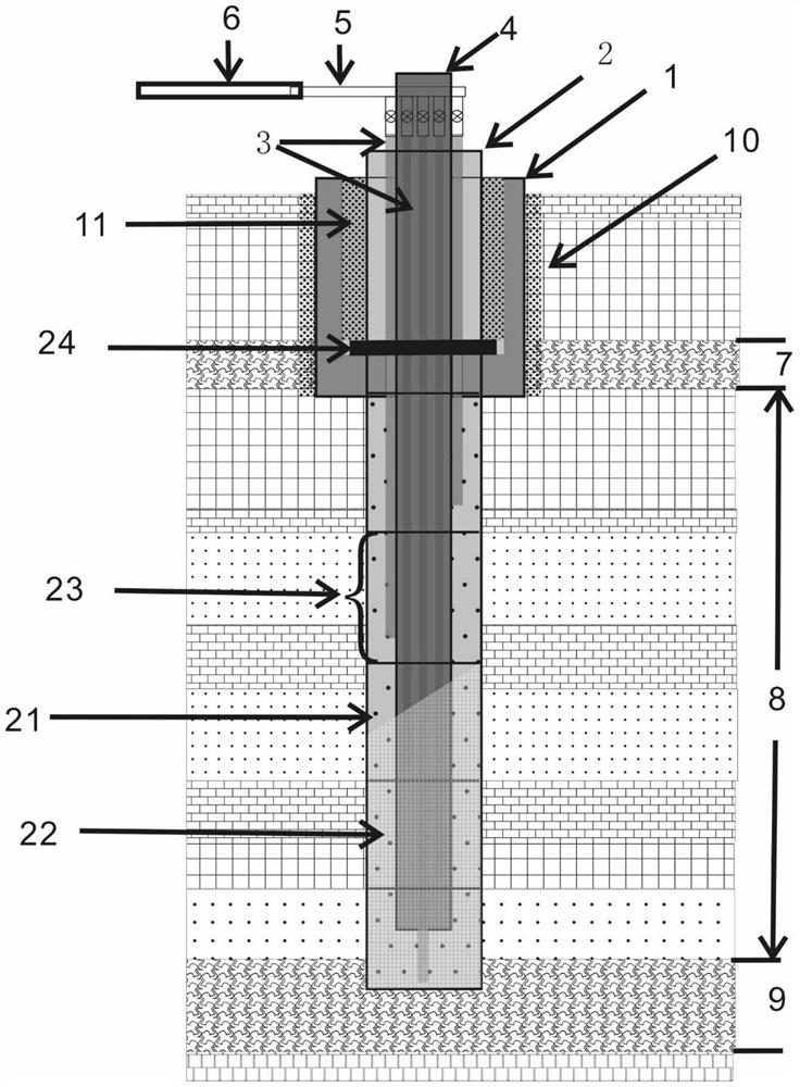
[0024] figure 1 It is a schematic diagram of the cross-sectional structure of the gas injection hole in the embodiment of the present invention.

[0025] refer to figure 1 shown, as figure 1 As shown, the gas injection hole system for placing the gas injection pipe includes:

[0026] Multiple gas injection pipes (3), cementing casing (1), gas inj...


PUM


Abstract

The invention provides a construction method of a gas injection hole. The construction method comprises the following steps that an upper water-resisting layer (7) is penetrated by using a phi 150mm drill bit, then a phi 150mm well cementation sleeve (1) is lowered, and the outer side of the well cementation sleeve (1) is fixed by using a magnesium-based cementing material in an out-of-wall grouting mode to form an out-of-pipe cement body (10); a fine debris water-containing layer (8) is drilled in the well cementation sleeve (1) by using a phi 110mm drill bit, and a lower water-resisting layer (9) is drilled; a drill bit with the diameter phi of 127 mm is drilled into the upper water-resisting layer (7) by the depth of 0.2-1 m in the well cementation sleeve (1), so that a closed steel ring (24) of a gas injection screen pipe (2) is embedded into the upper water-resisting layer (7); and the processed gas injection screen pipe (2) is put into the well cementation sleeve (1), and then amagnesium-based cementing material is poured to form an in-of-pipe cement body and enable the in-of-pipe cement body (11) to be cemented and fixed with the well cementation sleeve (1). According to the construction method of the gas injection hole, air with certain pressure can be injected into the water-containing layer, so that pore brine of the water-containing layer is rapidly discharged, thebrine mining cost can be reduced, the brine mining amount is greatly increased, and the mining efficiency and the recovery ratio are improved.

Description

technical field [0001] This application relates to a construction method of air injection holes in an air-driven brine extraction system, in particular, to a method of using air to drive the injection of brine to increase the brine feedwater in the aquifer under the conditions of low porosity, low feedwater, and low permeability. The construction method of air hole. Background technique [0002] my country's potash resources account for only 2% of the world's proven reserves, but its production accounts for 15% of global output, and my country's potash fertilizer consumption accounts for 25% of global consumption; moreover, 97% of my country's potash resources % are brine-type salt lake deposit resources in Qinghai and Xinjiang. Through high-intensity mining in recent decades, some salt lakes have no brine to be recovered, and most of the subsurface brine mines in the salt rock formations of the salt lakes have been exhausted, especially the salt lakes in the Qaidam Basin. ...

Claims


Application Information

Patent Timeline
Patent Type & Authority Applications(China)
IPC IPC(8): E21B7/00E21B33/13E21B43/16
CPCE21B7/00E21B33/13E21B43/166
Inventor 山成梁山成祥山成栋山俊杰
Owner 青海凹口凸钾镁盐技术有限公司
Why Eureka
Try Eureka