Check patentability & draft patents in minutes with Patsnap Eureka AI!

Steam ejector

An ejector and steam technology, applied in the directions of jet pumps, machines/engines, non-displacement pumps, etc., can solve the problems of easy deviation of the air nozzle, reduced working performance, strong airflow noise, etc., to achieve convenient manufacturing, low cost, and use long life effect

Inactive Publication Date: 2021-02-02
连云港佑丰电力设备有限公司
View PDF6 Cites 0 Cited by
  • Summary
  • Abstract
  • Description
  • Claims
  • Application Information

AI Technical Summary

Problems solved by technology

[0004] The technical solution of the present invention to solve the technical problem is: the air nozzle is designed to be connected to the blower and the horn, the blower (4) and the horn (5) are connected as one, and a suction device is arranged in the middle of the blower. The air hole is used for air inhalation; the air nozzle structure is formed to solve the problem that the air nozzle is easy to deviate, produces strong air flow noise, and reduces the working performance; and a vacuum adjustment device is installed on the upper cover

Method used


Image

  • Steam ejector
  • Steam ejector
  • Steam ejector

Examples


Embodiment 1

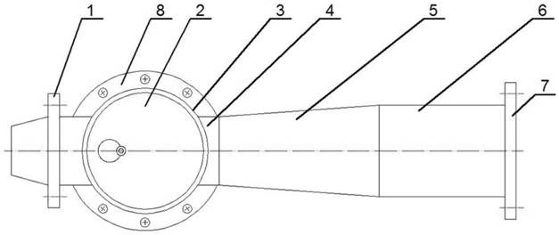
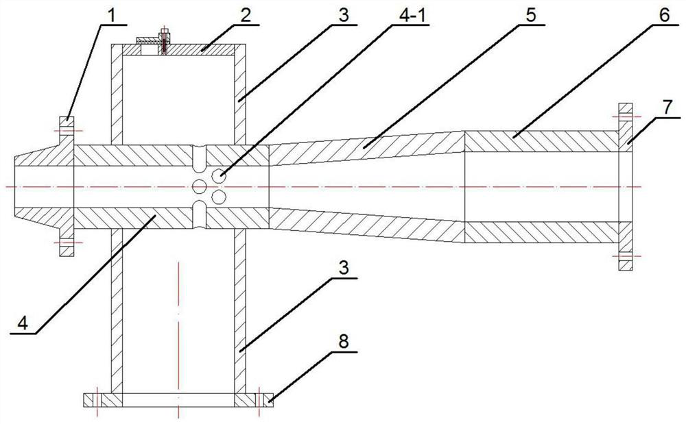
[0029] exist figure 1 , figure 2 Among them, the present invention mainly consists of flange A (1), upper cover (2), suction cylinder (3), blowing cylinder (4), trumpet (5), air mixing cylinder (6), flange B (7) , Flange C (8) composition.

[0030] The right end of the flange A (1) is connected to the air blower (4), and the air blower (4) is strung on the middle and upper part of the inhaler (3) and fixedly connected; the right end of the air blower (4) It is connected with the left end of the trumpet (5), the right end of the horn (5) is connected with the left end of the air mixing cylinder (6), and the right end of the air mixing cylinder (6) is connected with the left end of the flange B (7); The lower end of the suction cylinder (3) is connected to the upper end of the flange C (8), and the upper end of the suction cylinder (3) is connected to the upper cover (2).

[0031] The left part of the flange A (1) has a tapered body for connecting the steam channel.

[003...

Embodiment 2

[0044] exist figure 1 , figure 2 Among them, the present invention mainly consists of flange A (1), upper cover (2), suction cylinder (3), blowing cylinder (4), trumpet (5), air mixing cylinder (6), flange B (7) , Flange C (8) composition.

[0045] The right end of the flange A (1) is connected with the air blower (4), and the air blower (4) is strung on the middle and upper part of the suction tube (3) and fixedly connected; the right end of the air blower (4) It is connected with the left end of the horn (5), the right end of the horn (5) is connected with the left end of the air mixing cylinder (6), and the right end of the air mixing cylinder (6) is connected with the left end of the flange B (7); The lower end of the suction cylinder (3) is connected to the upper end of the flange C (8), and the upper end of the suction cylinder (3) is connected to the upper cover (2).

[0046] The left part of the flange A (1) has a tapered body for connecting the steam channel.

...


PUM


Abstract

A steam ejector is mainly composed of a flange A (1), an upper cover (2), an air suction cylinder (3), an air blowing cylinder (4), a horn cylinder (5), an air mixing cylinder (6), a flange B (7) anda flange C (8). The steam ejector is characterized in that a vacuum adjusting device is arranged on the upper cover (2); the adjusting device is composed of an adjusting cover (2-2), an adjusting bolt(2-3), a sealing gasket (2-4), an adjusting hole (2-5) and a screw hole (2-6); the steam ejector has the beneficial effects that the structure is simple, manufacturing is convenient, cost is low, work is stable, efficiency is high, the service life is long, safety performance is improved, and the proper vacuum degree is obtained; and very good benefits can be brought to production units and users.

Description

technical field [0001] The invention relates to a steam jet equipment, especially a steam injector. Background technique [0002] The steam ejector is a vacuum acquisition device that uses fluid to transfer energy and mass. Steam with a certain pressure is sprayed out through nozzles that are symmetrically arranged with a certain side slope and converged at a focal point. Due to the particularly high flow rate of the jet steam, the pressure energy is converted into velocity energy, and the pressure in the suction area is reduced to generate a vacuum. It is mainly used in the vacuum suction process of various industries; however, the structure of the steam ejector in the prior art is complex, difficult to manufacture, low in efficiency, especially the gas nozzle is easy to deviate, which reduces the working performance, and is easy to be damaged when the steam pressure is extremely high equipment and vacuum container, so it is desired to have a steam ejector with simple stru...

Claims


Application Information

Patent Timeline
Patent Type & Authority Applications(China)
IPC IPC(8): F04F5/20F04F5/52
CPCF04F5/20F04F5/52
Inventor 柴前进
Owner 连云港佑丰电力设备有限公司
Features
  • R&D
  • Intellectual Property
  • Life Sciences
  • Materials
  • Tech Scout
  • Unparalleled Data Quality
  • Higher Quality Content
  • 60% Fewer Hallucinations
Learn More