Humidity control method of fresh air system

A technology for humidity control and fresh air system, applied in ventilation systems, heating and ventilation control systems, heating and ventilation safety systems, etc.

Active Publication Date: 2021-02-02
QINGDAO HAIER AIR CONDITIONING ELECTRONICS CO LTD +2
View PDF6 Cites 4 Cited by
  • Summary
  • Abstract
  • Description
  • Claims
  • Application Information

AI Technical Summary

Problems solved by technology

[0005]In order to solve the above-mentioned problems in the prior art, that is, in order to solve the problem that the existing fresh air system cannot adjust the humidity of the fresh air well and lead to poor comfort of the fresh air, this The invention provides a method for controlling the humidity of a fresh air system. The fresh air system includes a housing and a humidity adjustment member rotatably arranged in the housing. The housing is formed with first fresh air passages, The second fresh air channel, the third fresh air channel and the fourth fresh air channel, the first fresh air channel communicates with the indoor air outlet and the first fresh air channel is provided with an indoor fresh air unit, the second fresh air channel is connected to the indoor return The air outlets are connected, and the second fresh air channel is provided with an indoor heating component, the third fresh air channel is connected with the outdoor air outlet, and the third fresh air channel is provided with an outdoor fresh air unit, and the fourth fresh air channel is connected to the outdoor air outlet. The outdoor air inlets are connected, and an outdoor heating component is arranged in the fourth fresh air passage, and the humidity regulating component includes a first humidity regulating core and a second humidity regulating core independently arranged, and the first humidity regulating core The body and the second humidity adjustment core are set to be able to absorb moisture under non-high-temperature ai

Method used


Image

  • Humidity control method of fresh air system
  • Humidity control method of fresh air system
  • Humidity control method of fresh air system

Examples


Embodiment Construction

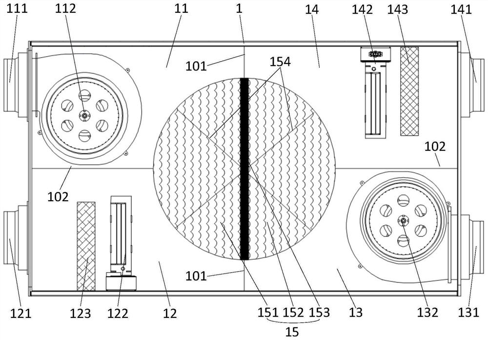
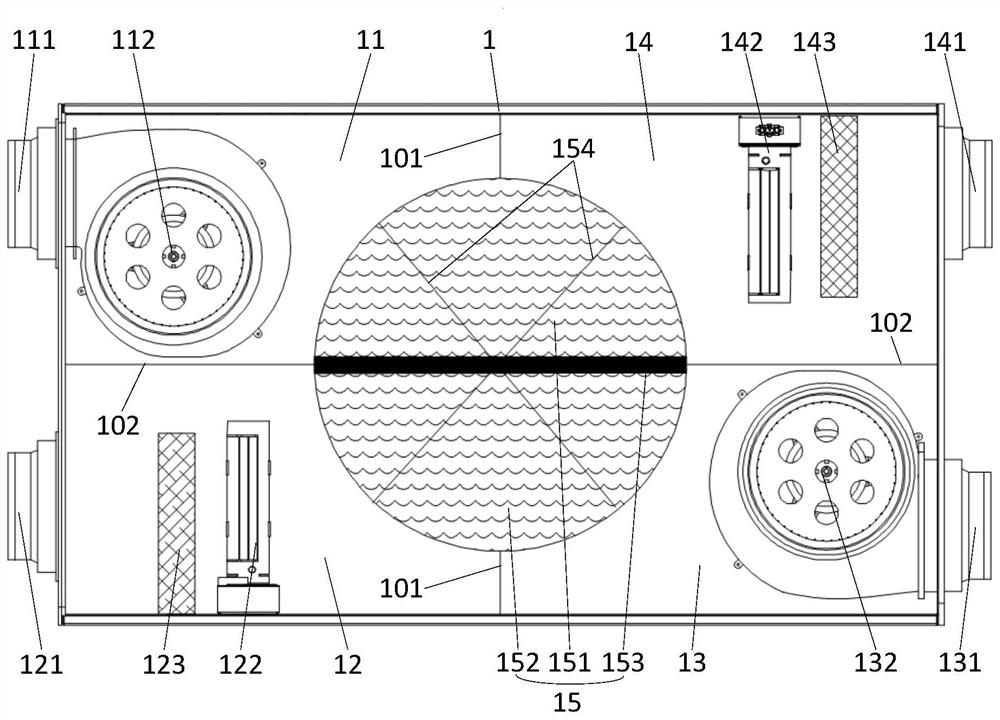
[0028] Preferred embodiments of the present invention are described below with reference to the accompanying drawings. Those skilled in the art should understand that these embodiments are only used to explain the technical principles of the present invention, and are not intended to limit the protection scope of the present invention. Those skilled in the art can adjust it according to actual needs, so as to adapt to specific application occasions. It should be noted that, in the description of the present invention, the terms "up", "down", "left", "right", "horizontal", "vertical", "vertical", "horizontal", "center", Terms such as "inner", "outer" and other indicated directions or positional relationships are based on the directions or positional relationships shown in the drawings, which are for convenience of description only, and do not indicate or imply that the device or element must have a specific orientation , constructed and operated in a particular orientation and...


PUM


Abstract

The invention belongs to the technical field of fresh air, and particularly provides a humidity control method of a fresh air system. The humidity control method aims to solve the problem that an existing fresh air system cannot well adjust the humidity of fresh air, and consequently the comfort degree of the fresh air is poor. Therefore, the fresh air system comprises a shell and a humidity adjusting component rotatably arranged in the shell. The humidity control method can control the rotating position of the humidity adjusting component according to the fresh air supply requirement, so thatthe fresh air system can selectively supply fresh air according to the use requirement of a user; the opening and closing states of an indoor heating component and an outdoor heating component are controlled through the rotating position of the humidity adjusting component and the indoor relative humidity, so that the fresh air system can correspondingly start a humidifying function or a dehumidifying function according to the humidity adjusting requirement, and the humidity of the fresh air is effectively controlled; and therefore, the indoor relative humidity is controlled to be always keptin a proper range to the greatest extent, so that the user experience is effectively improved.

Description

technical field [0001] The invention belongs to the technical field of fresh air, and specifically provides a humidity control method for a fresh air system. Background technique [0002] With the continuous development of fresh air technology, users have higher and higher requirements for the quality of fresh air supplied by the fresh air system. Take the humidity of the fresh air as an example. When the fresh air system is used in some areas with excessive humidity or in the rainy season with heavy humidity, the introduction of a large amount of humid air will inevitably cause discomfort to users; or, when the fresh air system is used in some areas with excessive humidity. When used in a small area or in the dry autumn and winter seasons, the introduction of a large amount of dry air will inevitably cause discomfort to the user. Under these circumstances, the humidity adjustment capability of the fresh air system is particularly important. Only when the fresh air system c...

Claims


Application Information

Patent Timeline
IPC IPC(8): F24F7/08F24F11/64F24F11/65F24F11/86F24F13/02F24F13/20F24F13/28F24F110/20F24F110/22
CPCF24F7/08F24F13/02F24F13/20F24F13/28F24F11/64F24F11/65F24F11/86F24F2110/20F24F2110/22Y02B30/70
Inventor 李银银宋强刘江彬任滔
Owner QINGDAO HAIER AIR CONDITIONING ELECTRONICS CO LTD
Why Eureka
Try Eureka