Liftable HUD device

A technology of mounting plate and mounting table, applied in the field of head-up display, can solve the problems of easily blocking the driver's line of sight, potential safety hazards, and the space occupied by the screw rod.

Inactive Publication Date: 2021-02-05
张宇森
View PDF1 Cites 2 Cited by
  • Summary
  • Abstract
  • Description
  • Claims
  • Application Information

AI Technical Summary

Problems solved by technology

[0002] Head-up display (HUD) for short, can project important information on the windshield, and the driver can obtain information from the windshield without bowing his head. However, there is a large difference in the height of the driver. The existing head-up display is suitable for driving Due to the difference in the height of the driver, a support frame is often installed to adjust the projection height of the head-up display. In order to facilitate the rotation and adjustment of the angle of the head-up display, the support frame is generally set higher, so it is easy to block the driver's line of sight and cause a safety hazard.
[0003] In the prior art, Chinese patent authorization number: CN210069328U patent, publication date: 2020-02-04, a HUD device that can be raised and lowered, including a base, a housing, a motor, a fixed frame and a retractable support frame, the b

Method used


Image

  • Liftable HUD device
  • Liftable HUD device

Examples


Embodiment 1

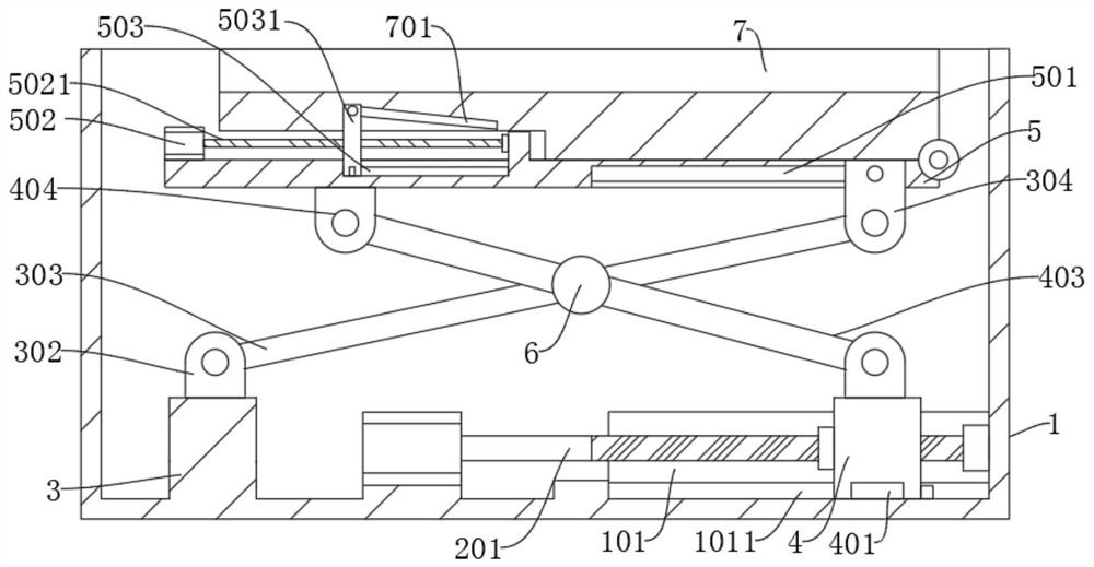
[0021] refer to Figure 1-2 , a liftable HUD device, comprising a mounting box 1, a mounting plate 5 and a placement table 7, the mounting plate 5 is arranged in the mounting box 1, the placing table 7 is rotatably connected to the mounting plate 5, and the bottom inner wall of the mounting box 1 From left to right, the first installation platform 3 and the first motor 2 are fixedly connected in sequence, the output end of the first motor 2 is fixedly connected with the first threaded rod 201, and the end of the first threaded rod 201 away from the first motor 2 is rotatably connected to the On the inner wall of the side wall of the installation box 1, the second mounting platform 4 is screwed on the first threaded rod 201, and the top of the first mounting platform 3 is connected with a first adjusting rod 303 in rotation, and the top of the second mounting platform 4 is connected in rotation. There is a second adjusting rod 403, the first adjusting rod 303 and the second adj...

Embodiment 2

[0025] refer to Figure 1-2 , a liftable HUD device, comprising a mounting box 1, a mounting plate 5 and a placement table 7, the mounting plate 5 is arranged in the mounting box 1, the placing table 7 is rotatably connected to the mounting plate 5, and the bottom inner wall of the mounting box 1 From left to right, the first installation platform 3 and the first motor 2 are fixedly connected in sequence, the output end of the first motor 2 is fixedly connected with the first threaded rod 201, and the end of the first threaded rod 201 away from the first motor 2 is rotatably connected to the On the inner wall of the side wall of the installation box 1, the second mounting platform 4 is screwed on the first threaded rod 201, and the top of the first mounting platform 3 is connected with a first adjusting rod 303 in rotation, and the top of the second mounting platform 4 is connected in rotation. There is a second adjusting rod 403, the first adjusting rod 303 and the second adj...


PUM


Abstract

The invention discloses a liftable HUD device, and belongs to the technical field of head-up display. The liftable HUD device comprises a mounting box, a mounting plate and a placement table; the mounting plate is arranged in the mounting box, the placement table is rotatably connected to the mounting plate, a first mounting table and a first motor are fixedly connected to the inner wall of the bottom of the mounting box in sequence from left to right, and a first threaded rod is fixedly connected to the output end of the first motor; the end, away from the first motor, of the first threaded rod is rotationally connected to the inner wall of the side wall of the mounting box, and the first threaded rod is in threaded connection with a second mounting table. According to the device, the HUDdisplayer can be fixed more stably through cooperation of a third threaded rod and a clamping plate, the height and the angle are automatically adjusted through a first motor, a user can adjust the angle more conveniently, secondary adjustment can be conducted on the angle through a second motor, and the device is suitable for drivers with different driving habits.

Description

technical field [0001] The present invention relates to the technical field of head-up display technology, in particular to a liftable HUD device. Background technique [0002] Head-up display (HUD) for short, can project important information on the windshield, and the driver can obtain information from the windshield without bowing his head. However, there is a large difference in the height of the driver. The existing head-up display is suitable for driving Because of the difference in the height of the driver, a support frame is often installed to adjust the projection height of the head-up display. In order to facilitate the rotation and adjustment of the angle of the head-up display, the support frame is generally set higher, so it is easy to block the driver's line of sight and cause a safety hazard. [0003] In the prior art, Chinese patent authorization number: CN210069328U patent, publication date: 2020-02-04, a HUD device that can be raised and lowered, including ...

Claims


Application Information

Patent Timeline
IPC IPC(8): B60R11/02F16M11/04F16M13/02
CPCB60R11/0229B60R2011/0026B60R2011/0092F16M11/04F16M13/02
Inventor 张宇森
Owner 张宇森
Why Eureka
Try Eureka