Trigger type heavy object lifting transportation device
A lifting and transporting and triggering technology, which is applied in the direction of lifting devices, lifting frames, etc., can solve the problems of slow transportation and worker fatigue
- Summary
- Abstract
- Description
- Claims
- Application Information
AI Technical Summary
Problems solved by technology
Method used
Image
Examples
Embodiment 1
[0022] A trigger type heavy object lifting and transporting device, such as figure 1 As shown, it includes a frame 1, a servo motor 2, an engaging mechanism 3, a forward and reverse mechanism 4, and a lifting mechanism 5. The front side of the upper part of the frame 1 is provided with a servo motor 2, and the upper part of the frame 1 is provided with an engaging mechanism 3. The upper part of the frame 1 is provided with a forward and reverse mechanism 4, and the forward and reverse mechanism 4 is connected with the engaging mechanism 3, and the upper part of the frame 1 is provided with a lifting mechanism 5.
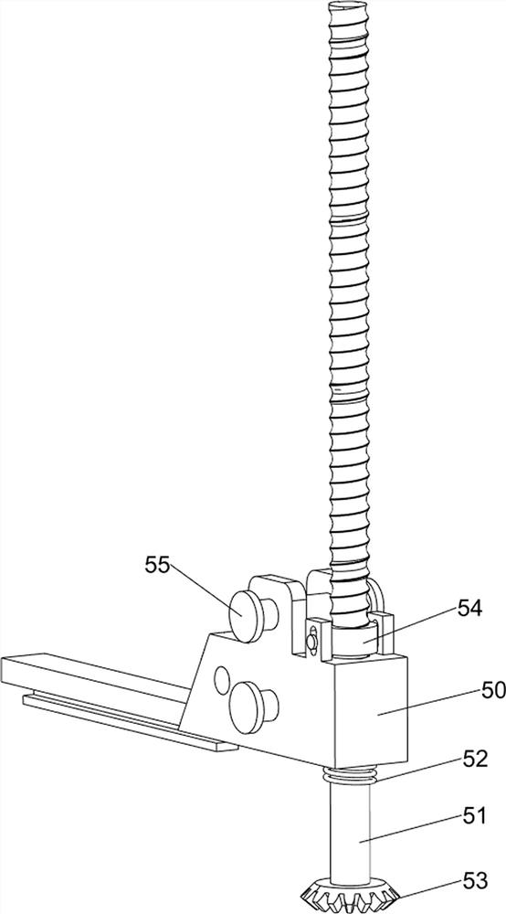
[0023] When the user needs to lift and transport heavy objects, this device can be used. First, the heavy objects to be lifted are placed on the lifting mechanism 5, then the servo motor 2 is turned on, and the servo motor 2 drives the meshing mechanism 3 and then the forward and reverse mechanism 4 to operate, the forward and reverse mechanism 4 drives the lifting m...
Embodiment 2
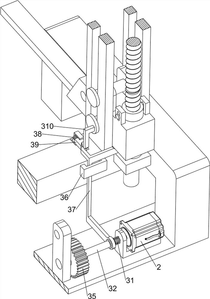
[0025] On the basis of Example 1, such as Figure 2-6 As shown, the engagement mechanism 3 includes a T-shaped frame 30, a first spring 31, a sleeve 32, a first connecting rod 33, an engagement block 34, a first gear 35, a limit block 36, a special-shaped push rod 37, and a second spring 38. The first wedge-shaped block 39 and the T-shaped bar 310. The output shaft of the servo motor 2 is provided with a T-shaped frame 30. The output shaft of the servo motor 2 is movable with a sleeve 32. Between the frame 1 and the sleeve 32 A first spring 31 is connected between them, and the first spring 31 is set on the output shaft of the servo motor 2. The sleeve 32 is symmetrically rotated on the left side and is provided with a first connecting rod 33, and the first connecting rod 33 on both sides is rotated. An engaging block 34 is provided, and a first gear 35 is provided in the middle of the front side of the frame 1. The engaging block 34 and the T-shaped frame 30 are both located ...
Embodiment 3
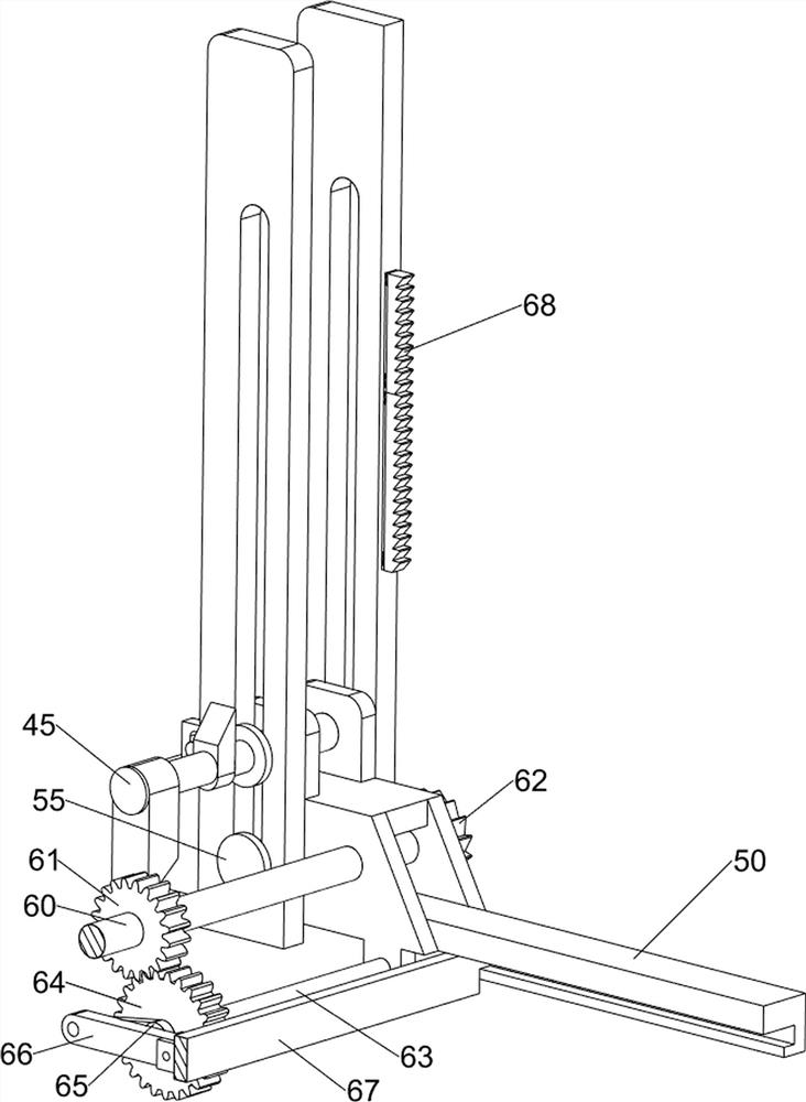
[0032] On the basis of Example 2, such as Figure 7 As shown, push mechanism 6 is also included, and push mechanism 6 includes first rotating shaft 60, third gear 61, ratchet gear 62, second rotating shaft 63, fourth gear 64, crank 65, second connecting rod 66, push plate 67 and ratchet bar 68, the load-bearing frame 50 on both sides is rotatably provided with the first rotating shaft 60, is provided with the 3rd gear 61 and ratchet gear 62 on the first rotating shaft 60, the load-bearing frame 50 lower side of the left side is rotatable A second rotating shaft 63 is provided, and a fourth gear 64 is arranged on the second rotating shaft 63. The fourth gear 64 meshes with the third gear 61. The second rotating shaft 63 is provided with a crank 65, and the crank 65 is rotatably provided with a second connection. Rod 66, sliding type is provided with push plate 67 between the load-bearing frames 50 on both sides, and push plate 67 is connected with the second connecting rod 66 r...
PUM
 Abstract
Description
Claims
Application Information
 - R&D
- Intellectual Property
- Life Sciences
- Materials
- Tech Scout
- Unparalleled Data Quality
- Higher Quality Content
- 60% Fewer Hallucinations
Browse by: Latest US Patents, China's latest patents, Technical Efficacy Thesaurus, Application Domain, Technology Topic, Popular Technical Reports.
© 2025 PatSnap. All rights reserved.Legal|Privacy policy|Modern Slavery Act Transparency Statement|Sitemap|About US| Contact US: help@patsnap.com


