A trigger type lifting and transporting device for heavy objects

A lifting and transporting, triggering technology, applied in the direction of lifting devices, lifting frames, etc., can solve the problems of tired workers and slow transportation

Active Publication Date: 2022-07-12
佛山朗利金属制品有限公司
View PDF3 Cites 0 Cited by
  • Summary
  • Abstract
  • Description
  • Claims
  • Application Information

AI Technical Summary

Problems solved by technology

[0004] In order to overcome the shortcomings of manual handling or lifting and lowering of heavy objects by tools, the workers are tired and the transportation speed is slow, the technical problem of the present invention is: to provide a method that can automatically transport heavy objects and can Trigger type heavy object lifting transport device that pushes out heavy objects

Method used


Image

  • A trigger type lifting and transporting device for heavy objects
  • A trigger type lifting and transporting device for heavy objects
  • A trigger type lifting and transporting device for heavy objects

Examples


Embodiment 1

[0022] A trigger type lifting and transporting device for heavy objects, such as figure 1 As shown, it includes a frame 1, a servo motor 2, a meshing mechanism 3, a forward and reverse rotation mechanism 4 and a lifting mechanism 5. The front side of the upper part of the frame 1 is provided with a servo motor 2, and the upper part of the frame 1 is provided with a meshing mechanism 3. The upper part of the frame 1 is provided with a forward and reverse rotation mechanism 4, and the forward rotation mechanism 4 is connected with the meshing mechanism 3, and the upper part of the frame 1 is provided with a lifting mechanism 5.

[0023] When the user needs to lift and transport heavy objects, he can use this device. First, place the heavy objects that need to be lifted and lowered on the lifting mechanism 5, then turn on the servo motor 2, and drive the meshing mechanism 3 through the servo motor 2 to forward and reverse the mechanism. 4 to operate, the lifting mechanism 5 is dr...

Embodiment 2

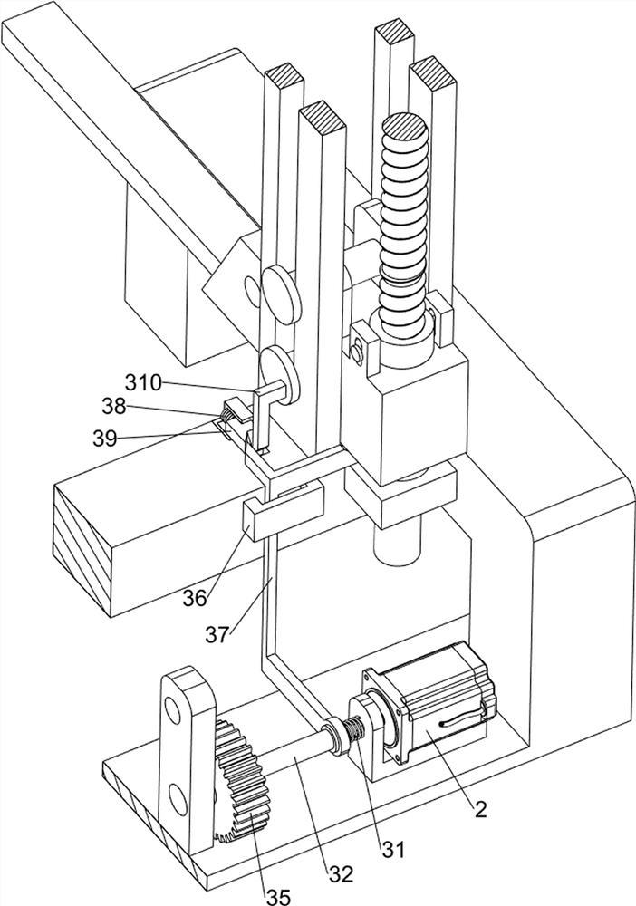
[0025] On the basis of Example 1, as Figure 2-6 As shown, the meshing mechanism 3 includes a T-shaped frame 30, a first spring 31, a sleeve 32, a first connecting rod 33, a meshing block 34, a first gear 35, a limit block 36, a special-shaped push rod 37, and a second spring 38. The first wedge block 39 and the T-bar 310, a T-frame 30 is arranged on the output shaft of the servo motor 2, and a sleeve 32 is movably arranged on the output shaft of the servo motor 2. A first spring 31 is connected between them, the first spring 31 is sleeved on the output shaft of the servo motor 2, the left side of the sleeve 32 is symmetrically rotated with a first connecting rod 33, and the first connecting rods 33 on both sides are all rotating. A meshing block 34 is provided, a first gear 35 is rotatably provided in the middle of the front side of the frame 1, the meshing block 34 and the T-shaped frame 30 are both located inside the first gear 35, and a limit block 36 is arranged on the fr...

Embodiment 3

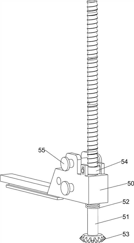
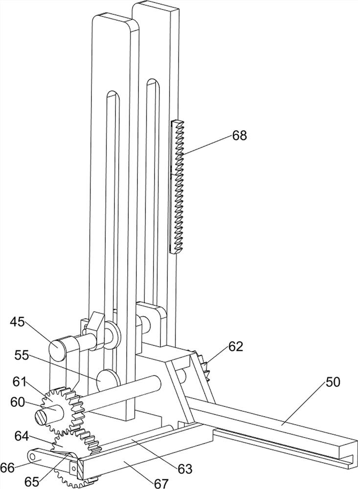
[0032] On the basis of Example 2, as Figure 7 As shown, a push mechanism 6 is also included. The push mechanism 6 includes a first rotating shaft 60, a third gear 61, a ratchet gear 62, a second rotating shaft 63, a fourth gear 64, a crank 65, a second connecting rod 66, and a push plate. 67 and the ratchet rack 68, the first rotating shaft 60 is rotatably arranged between the bearing frames 50 on both sides, the first rotating shaft 60 is provided with a third gear 61 and a ratchet gear 62, and the lower side of the bearing frame 50 on the left side is rotatable. There is a second rotating shaft 63, a fourth gear 64 is arranged on the second rotating shaft 63, the fourth gear 64 meshes with the third gear 61, a crank 65 is arranged on the second rotating shaft 63, and a second connection is rotatably arranged on the crank 65 Rod 66, a push plate 67 is slidably provided between the load-bearing frames 50 on both sides, and the push plate 67 is rotatably connected with the sec...


PUM


Abstract

The invention relates to a transport device, in particular to a trigger type lifting and transport device for heavy objects. The technical problem of the present invention is to provide a trigger-type lifting and transporting device for heavy objects that can automatically transport heavy objects and has a fast transportation speed. A trigger type lifting and transporting device for heavy objects, comprising: a frame, the frame is used to install the whole device; a servo motor, the servo motor is arranged on one side of the upper part of the frame; a meshing mechanism, the meshing mechanism is arranged on the upper part of the frame; The rotating mechanism, the forward and reverse rotation mechanism is arranged on the upper part of the frame, and the forward and reverse rotation mechanism is connected with the meshing mechanism; the lifting mechanism, the lifting mechanism is arranged on the upper part of the frame. The present invention achieves the effect that the heavy objects can be transported automatically and can be pushed out; when the load-bearing frame is moved down and put in, the push mechanism is driven to move down, and with the cooperation of the push mechanism, the push mechanism can push the heavy objects down. The object is pushed out, so that there is no need to manually remove the heavy object.

Description

technical field [0001] The invention relates to a transport device, in particular to a trigger type lifting and transporting device for heavy objects. Background technique [0002] In the process of building buildings, people need to lift and transport building materials. In the process of transporting building materials, workers generally carry building materials manually, or build brackets at the location where they need to be transported, and pass the pulley block. Under the action of the worker, the required building materials are transported upwards by manually pulling the rope. In the above process of transporting the heavy objects, manual handling is required, or the heavy objects are lifted and lowered by means of tools. The workers are tired, and after the heavy objects are transported upward, the workers need to remove the heavy objects. [0003] Therefore, it is necessary to design a trigger-type lifting and transporting device for heavy objects that can automati...

Claims


Application Information

Patent Timeline
Patent Type & Authority Patents(China)
IPC IPC(8): B66F7/00B66F7/28
CPCB66F7/025B66F7/28
Inventor 赵庆省
Owner 佛山朗利金属制品有限公司
Why Eureka
Try Eureka