Micro-fluidic multi-gear flow regulator

A flow regulator and flow regulating valve technology, which is applied in valve devices, sliding valves, mechanical equipment, etc., can solve the problems of small size, low stability, and poor quantification of microfluidic flow regulators, so as to improve convenience and efficiency. Practicality, improved stability, improved reliability effects

Active Publication Date: 2021-02-05
SOUTHEAST UNIV
View PDF5 Cites 0 Cited by
  • Summary
  • Abstract
  • Description
  • Claims
  • Application Information

AI Technical Summary

Problems solved by technology

[0003] Traditional microfluidic flow regulators are small in size and complex in structure. Usually, the method of manually changing the pushing speed of the injection needle as an external drive is used to control the speed of liquid flow and the size of the flow. Therefore, the stability of the adjustment is low and the quantification is poor. and other shortcomings

Method used


Image

  • Micro-fluidic multi-gear flow regulator
  • Micro-fluidic multi-gear flow regulator
  • Micro-fluidic multi-gear flow regulator

Examples


Embodiment Construction

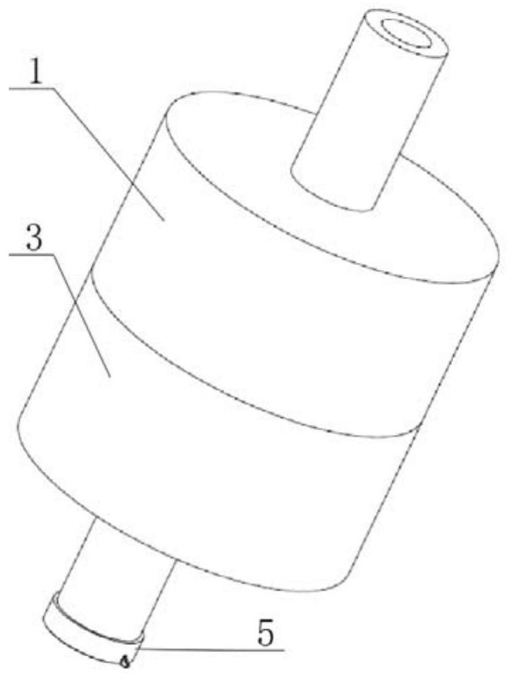
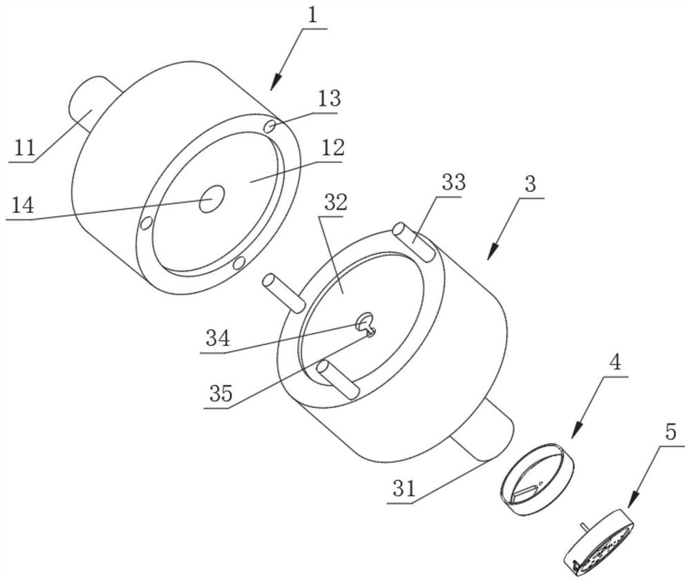
[0025] Such as figure 1 and figure 2 As shown, the microfluidic multi-position flow regulator of this embodiment includes an inflow part 1 and an outflow part 3 communicating with the inflow part 1, and a flow regulating valve is arranged at the outflow end of the outflow part 3 to adjust the flow rate. The valve includes a fixed baffle part 4, and the fixed baffle part 4 is rotationally connected with the adjusting baffle part 5;

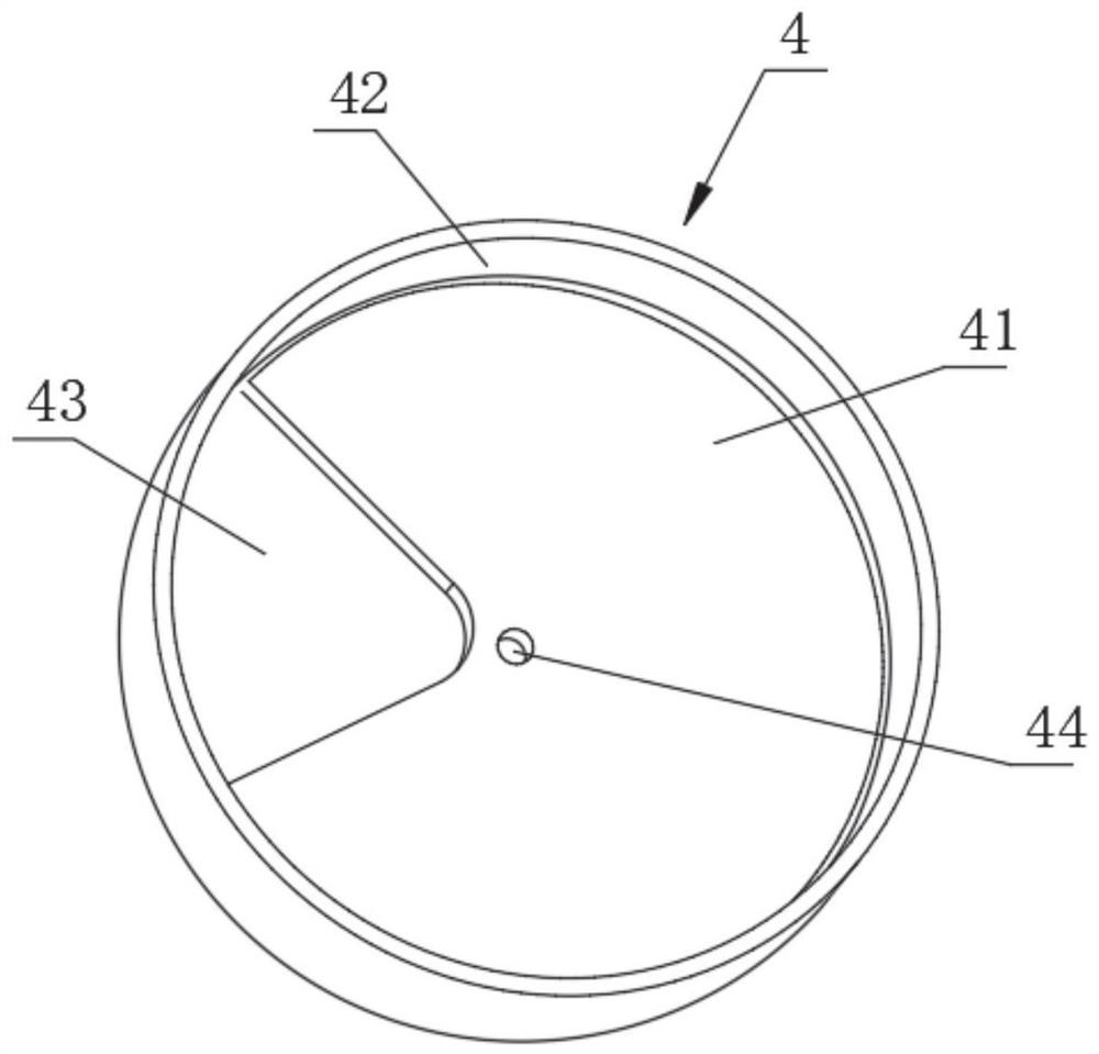
[0026] Such as image 3 and Figure 4 As shown, the fixed baffle part 4 has an outlet surface 41, which is provided with a fixing hole 43 communicating with the outlet end, and the adjustment baffle part 5 has a corresponding fitting with the outlet surface 41 and can be relatively rotated. The inflow surface 51 is provided with a plurality of hollow parts with different flow areas. When the inflow surface 51 rotates relative to the outflow surface 41, each hollow part makes the opening of the fixing hole 43 be covered with different areas. In...


PUM


Abstract

The invention relates to a micro-fluidic multi-gear flow regulator. The micro-fluidic multi-gear flow regulator comprises an inflow part and an outflow part communicating with the inflow part, a flowregulating valve is arranged at the outflow end of the outflow part and comprises a fixed baffle part, the fixed baffle part is rotationally connected to a regulating baffle part, the fixed baffle part is provided with an outflow face, the fixed baffle part is provided with a fixing hole communicating with the outflow end, the adjusting baffle part is provided with an inflow face which is correspondingly attached to the outflow face and can rotate relatively, the inflow face is provided with a plurality of hollowed-out parts different in overflowing area, when the inflow face rotates relativeto the outflow face, different areas of an orifice is covered with the hollowed-out parts, therefore, multi-stage adjustment of the overflowing area of the fixing hole is achieved, and the purpose ofmulti-stage adjustment of flow is achieved. According to the micro-fluidic multi-gear flow regulator, multi-gear quantitative regulation is achieved through the flow regulating valve, and the purposeof controlling the output flow is achieved by changing the area of a fluid outflow channel.

Description

technical field [0001] The invention relates to the technical field of flow regulators, in particular to a microfluidic multi-gear flow regulator. Background technique [0002] A microvalve is a key component of a microfluidic device, which generally requires a certain external driving force or its own force when the fluid flows to achieve the purpose of regulating the flow. Microvalve usually uses elastic polymer material film (polydimethylsiloxane PDMS) as the wall of the microchannel or arranges the elastic film inside the main channel, so as to generate a pressure difference on both sides of the elastic film to drive the deformation of the film. The function of regulating the flow rate of the main channel is achieved, and the structure is simple and the cost is low. [0003] Traditional microfluidic flow regulators are small in size and complex in structure. Usually, the method of manually changing the pushing speed of the injection needle as an external drive is used t...

Claims


Application Information

Patent Timeline
Patent Type & Authority Applications(China)
IPC IPC(8): F16K3/08F16K3/314
CPCF16K3/08F16K3/314
Inventor 陈盛智项楠邱雨孟润普
Owner SOUTHEAST UNIV
Why Eureka
Try Eureka