New energy automobile battery box with shock absorption function
A new energy vehicle, battery box technology, applied in the direction of secondary batteries, battery pack components, circuits, etc., can solve the problems of battery damage, poor heat dissipation effect of the battery box, etc., to reduce shaking, good shock absorption effect, Reduce the effect of line melting
- Summary
- Abstract
- Description
- Claims
- Application Information
AI Technical Summary
Problems solved by technology
Method used
Image

Examples
Embodiment 1
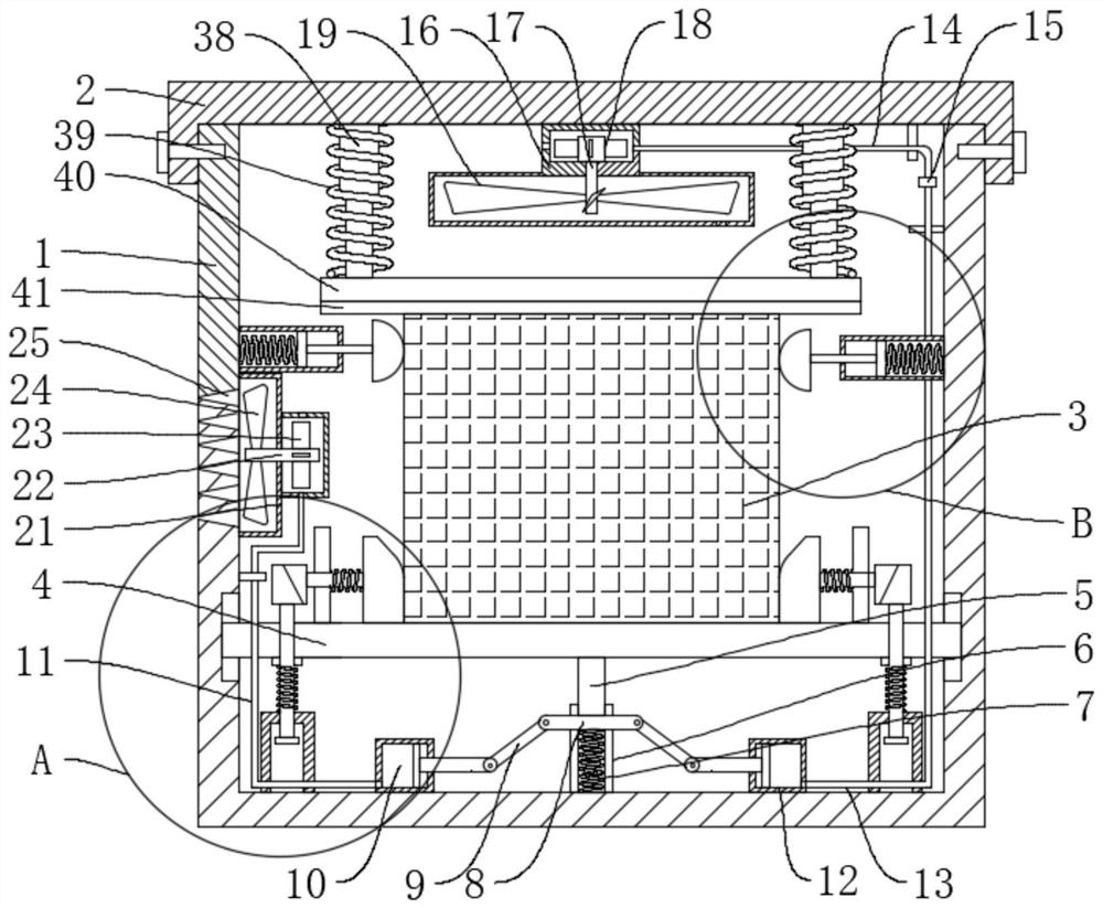
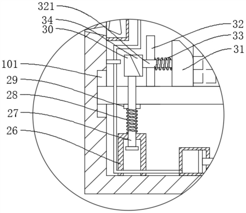
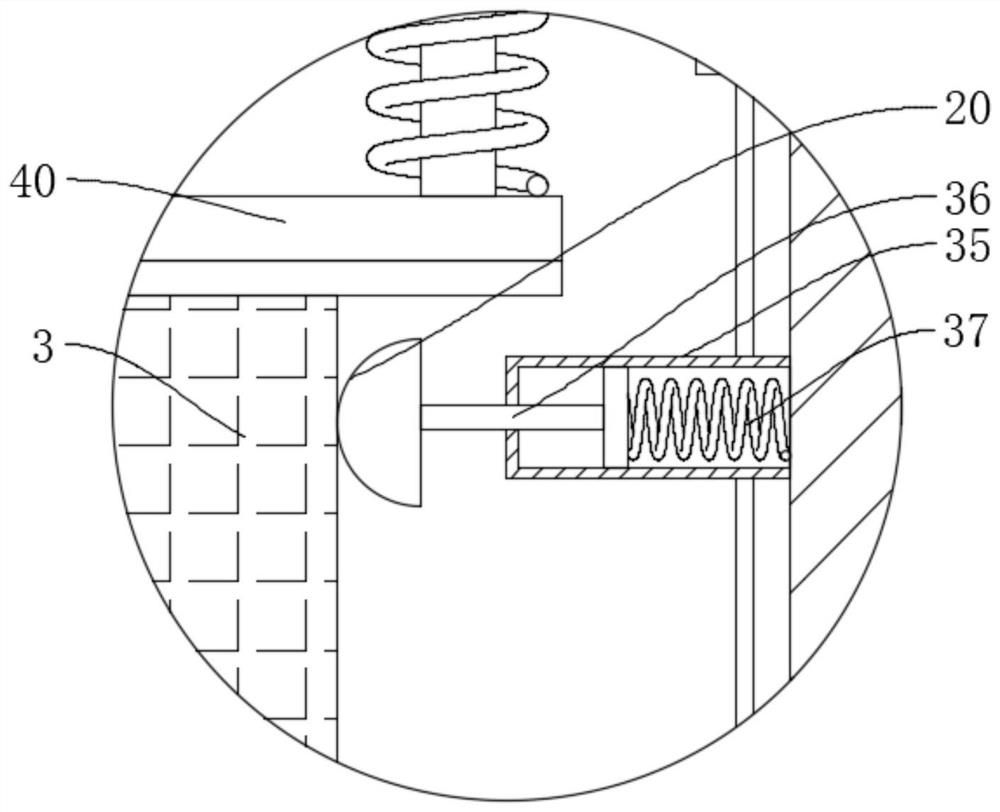
[0031] refer to figure 1 , Figure 4 , Figure 5 , Figure 6 , a new energy vehicle battery box with a shock absorbing function, including a box body 1, a box cover 2 and a battery 3, a support plate 4 is slidably connected to the box body 1, the battery 3 is placed on the support plate 4, and the support plate 4 The first sliding rod 5 is fixedly connected, and the end of the first sliding rod 5 away from the support plate 4 is fixedly connected with the slider 8, and the box body 1 is fixedly connected with the sliding sleeve 6, the first cylinder 10 and the second cylinder 12, and the sliding sleeve 6 is fixedly connected with the first spring 7, the first spring 7 is offset against the slider 8, the slider 8 is connected with the first cylinder 10 and the second cylinder 12 in rotation, and the box cover 2 is fixedly connected with the first convex frame 16 , the first convex frame 16 is rotatably connected with a cooling fan 19, the second cylinder 12 is connected with...
Embodiment 2
[0043] refer to figure 1 , figure 2 , a new energy vehicle battery box with a shock absorbing function, including a box body 1, a box cover 2 and a battery 3, a support plate 4 is slidably connected to the box body 1, the battery 3 is placed on the support plate 4, and the support plate 4 The first sliding rod 5 is fixedly connected, and the end of the first sliding rod 5 away from the support plate 4 is fixedly connected with the slider 8, and the box body 1 is fixedly connected with the sliding sleeve 6, the first cylinder 10 and the second cylinder 12, and the sliding sleeve 6 is fixedly connected with the first spring 7, the first spring 7 is offset against the slider 8, the slider 8 is connected with the first cylinder 10 and the second cylinder 12 in rotation, and the box cover 2 is fixedly connected with the first convex frame 16 , the first convex frame 16 is rotatably connected with a cooling fan 19, the second cylinder 12 is connected with the first convex frame 16...
Embodiment 3
[0055] refer to figure 1 , image 3 , a new energy vehicle battery box with a shock absorbing function, including a box body 1, a box cover 2 and a battery 3, a support plate 4 is slidably connected to the box body 1, the battery 3 is placed on the support plate 4, and the support plate 4 The first sliding rod 5 is fixedly connected, and the end of the first sliding rod 5 away from the support plate 4 is fixedly connected with the slider 8, and the box body 1 is fixedly connected with the sliding sleeve 6, the first cylinder 10 and the second cylinder 12, and the sliding sleeve 6 is fixedly connected with the first spring 7, the first spring 7 is offset against the slider 8, the slider 8 is connected with the first cylinder 10 and the second cylinder 12 in rotation, and the box cover 2 is fixedly connected with the first convex frame 16 , the first convex frame 16 is rotatably connected with a cooling fan 19, the second cylinder 12 is connected with the first convex frame 16 ...
PUM
 Abstract
Description
Claims
Application Information
 - R&D
- Intellectual Property
- Life Sciences
- Materials
- Tech Scout
- Unparalleled Data Quality
- Higher Quality Content
- 60% Fewer Hallucinations
Browse by: Latest US Patents, China's latest patents, Technical Efficacy Thesaurus, Application Domain, Technology Topic, Popular Technical Reports.
© 2025 PatSnap. All rights reserved.Legal|Privacy policy|Modern Slavery Act Transparency Statement|Sitemap|About US| Contact US: help@patsnap.com