Air freshener as well as preparation process and preparation system thereof

An air freshener and preparation system technology, which can be used in deodorization, disinfection and other directions, and can solve the problem of inability to form viscous liquid air fresheners.

Pending Publication Date: 2021-02-09
杜敏
View PDF3 Cites 2 Cited by
  • Summary
  • Abstract
  • Description
  • Claims
  • Application Information

AI Technical Summary

Problems solved by technology

However, the device cannot automatically condense and form the viscous liquid air freshener after mixing

Method used


Image

  • Air freshener as well as preparation process and preparation system thereof
  • Air freshener as well as preparation process and preparation system thereof
  • Air freshener as well as preparation process and preparation system thereof

Examples


specific Embodiment approach 1

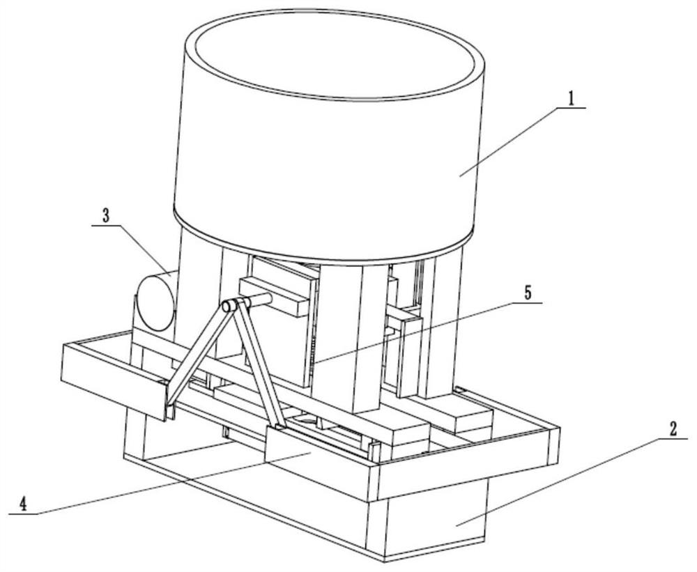
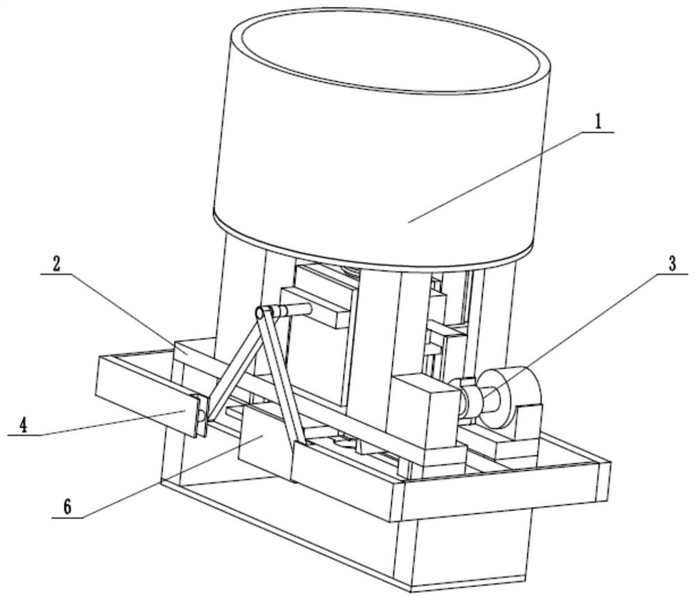
[0035] like Figure 1 to Figure 12 As shown, an air freshener preparation system includes a mixing and adding cylinder base 1, a processing base 2, an adding combination driver 3, a condensing molder 4, an automatic adding switch 5 and a drop combiner 6, and the mixing and adding cylinder base 1 Fixedly connected to the upper end of the processing base 2, the adding combination driver 3 is longitudinally reciprocatingly slidably connected in the processing base 2 and connected to the mixing and adding cylinder base 1, the condensation forming device 4 is fixedly connected to the front and rear ends of the adding combination driving device 3, and the condensation forming device 4 Slidingly connected in the processing base 2, the automatic adding switch 5 is fixedly connected to the lower end of the adding combination driver 3 and communicates with the adding combination driver 3 and the mixing and adding cylinder seat 1, and the drop combiner 6 is fixedly connected to the adding...

specific Embodiment approach 2

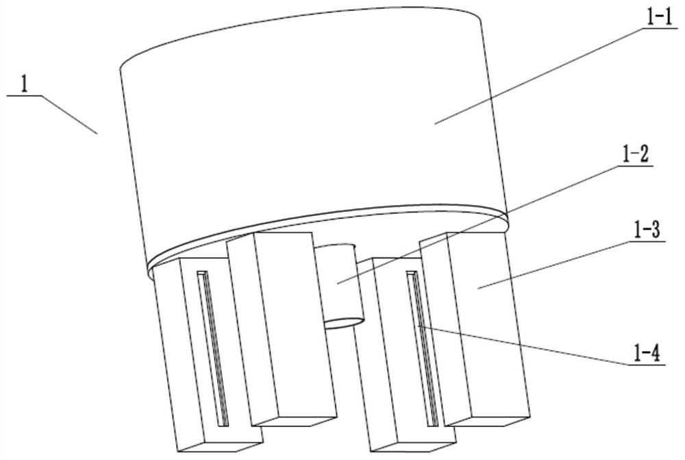
[0037] like Figure 1 to Figure 12 As shown, this embodiment will further describe Embodiment 1. The mixing and adding cartridge base 1 includes a mixing cylinder 1-1, a communicating adding pipe 1-2, four sliding support plates 1-3 and four T-shaped longitudinal The chute 1-4, the lower end of the mixing cylinder 1-1 is fixedly connected and communicated with the adding pipe 1-2, the four sliding support plates 1-3 are evenly fixed and connected to the lower end of the mixing cylinder 1-1, and the four T-shaped The longitudinal chute 1-4 is respectively arranged on the four sliding support plates 1-3. The viscous liquid air freshener formed by the mixing splint is stored in the mixing cylinder 1-1, and the viscous liquid air freshener is discharged through the connecting pipe 1-2.

specific Embodiment approach 3

[0039] like Figure 1 to Figure 12 As shown, this embodiment further explains the second embodiment. The processing base 2 includes a front fixing recess 2-1, a rear fixing recess 2-2, two longitudinal rectangular chute 2-3, and a motor fixing seat. 2-4, rotating shaft seat 2-5, lateral limit chute 2-6, center base plate 2-7, lower base 2-8, condensation extrusion slide seat 2-9, condensation extrusion chute 2-10, Two sliding seats 2-11 and forming drop round hole 2-12, front fixed recess 2-1 and rear fixed recess 2-2 are all fixedly connected on the center base plate 2-7, two longitudinal rectangular chute 2- 3 respectively vertically penetrate the front fixed recess 2-1 and the rear fixed recess 2-2, the rotating shaft seat 2-5 and the motor fixed seat 2-4 are fixedly connected to the front fixed recess 2-1 and the rear fixed seat 2-1 respectively On the concave seat 2-2, the lateral limit chute 2-6 runs through and is arranged between the front fixed concave seat 2-1 and t...


PUM


Abstract

The invention relates to the field of air fresheners, in particular to an air freshener as well as a preparation process and a preparation system thereof. The preparation process comprises the following steps: storing mixed viscous air cleaning agent liquid in a mixing-adding cylinder seat. Driven by an adding combined driver, the liquid in the mixing-adding cylinder seat equivalently falls on a processing base through an automatic adding switch during the downward displacement process of the reciprocating adding combined driver. The reciprocating adding combined driver enables the condensation former to move outwards during the downward displacement process, and during the upward displacement process of the adding combined driver, the automatic adding switch is turned off and the condensation former moves inwards at the same time, so that the viscous liquid is condensed, extruded and formed. The condensed and formed solid air freshener is dropped by a dropping combiner which is cooperated with the adding combined driver, and the process is repeated. The invention discloses an air freshener, which is prepared from essence, seaweed gel, surfactant, water and pigments.

Description

technical field [0001] The invention relates to the field of air fresheners, more specifically to an air freshener and its preparation process and preparation system. Background technique [0002] Patent No. CN201710110904.3 discloses a cloth winding device, especially relates to a cloth winding device for textile production. The technical problem to be solved by the present invention is to provide a cloth winding device for textile production that is easy to use, simple to operate, smooth to wind and cut, fast to cut, and to increase working speed. In order to solve the above technical problems, the present invention provides such a cloth winding device for textile production, which includes a base, a first slider, a screw, a first cylinder, a right side plate, a placement frame, a left side plate, a fixing plate, The first bearing seat, the first rotating shaft, the thumb cylinder, etc.; there is a chute on the right side of the base, and the sliding type in the chute is ...

Claims


Application Information

Patent Timeline
Patent Type & Authority Applications(China)
IPC IPC(8): A61L9/01A61L101/50A61L101/56
CPCA61L9/01A61L9/013A61L2209/21
Inventor 杜敏
Owner 杜敏
Why Eureka
Try Eureka