Candy can bottle cap packaging equipment for food processing
A technology for food processing and packaging equipment, which is applied in packaging and other directions, can solve the problems of easily broken candy jars, labor-intensive, slow capping efficiency, etc., and achieve the effect of avoiding the bottle body from tipping over
- Summary
- Abstract
- Description
- Claims
- Application Information
AI Technical Summary
Problems solved by technology
Method used
Image
Examples
Embodiment 1
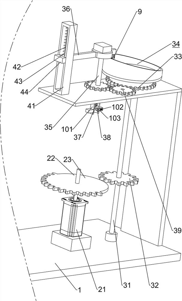
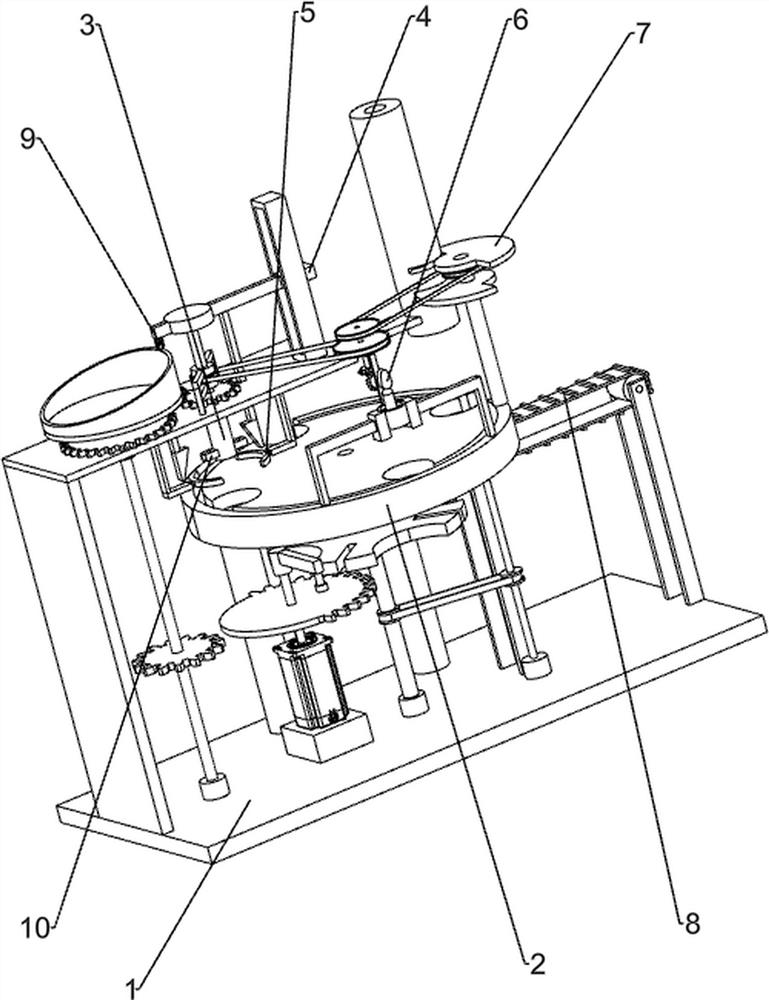
[0033] A kind of candy jar bottle cap packaging equipment for food processing, such as figure 1 As shown, it includes a base 1, a material transfer mechanism 2 and a twist cover mechanism 3. The material transfer mechanism 2 is provided in the middle of the lower part of the base 1, and the twist cover mechanism 3 is provided on the left side of the upper part of the base 1. The twist cover mechanism 3 and the material transfer mechanism 2 Cooperate.
[0034]When the workers need to cover the bottle caps after filling the fruit jars with candies, this kind of packaging equipment can be used. First, people put the bodies of four candy jars evenly on the transfer mechanism 2, and insert the bottle caps on the bottle caps. At the mouth, then start the material transfer mechanism 2, the operation of the material transfer mechanism 2 drives the bottle body to rotate intermittently, when a bottle body rotates to the bottom of the twist cap mechanism 3, the material transfer mechanis...
Embodiment 2
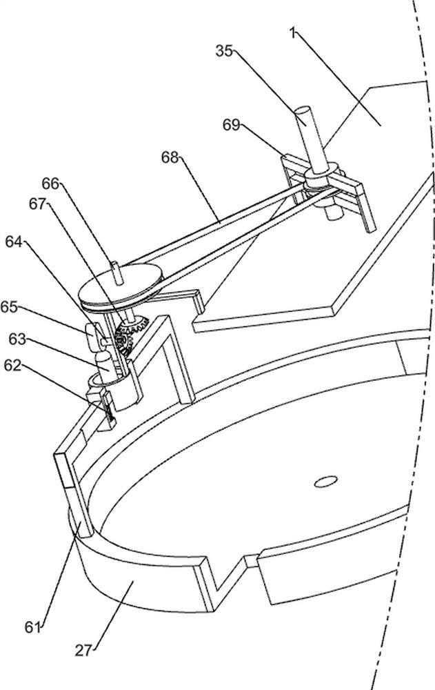
[0036] On the basis of Example 1, such as figure 2 , image 3 with Figure 4 As shown, the material transfer mechanism 2 includes a motor 21, a first rotating shaft 22, a missing gear 23, a dial block 24, a second rotating shaft 25, a first arc block 26, a first rotating disk 27 and a second rotating disk 28, and the bottom of the base 1 A motor 21 is installed in the middle of the left side, the output shaft of the motor 21 is connected with a first rotating shaft 22, the middle part of the first rotating shaft 22 is provided with a missing gear 23, the top of the first rotating shaft 22 is provided with a dial 24, and the middle of the bottom rear side of the base 1 is provided with The first rotating disk 27, the second rotating shaft 25 is rotationally connected between the bottom inner wall of the base 1 and the middle part of the first rotating disk 27, and the second rotating shaft 25 top is provided with a first arc-shaped block 26, and the first arc-shaped block 26 ...
Embodiment 3
[0041] On the basis of Example 2, such as image 3 , Figure 4 , Figure 5 , Image 6 with Figure 7 As shown, a guide mechanism 4 is also included. The right side of the top of the base 1 is provided with a guide mechanism 4. The guide mechanism 4 is slidably connected to the twist cover mechanism 3. The guide mechanism 4 includes a guide rail 41, a telescopic rod 42, and a second spring 43. And sliding sleeve 44, the right side of base 1 top is provided with guide rail 41, and sliding type is provided with sliding sleeve 44 in guide rail 41, and sliding sleeve 44 left wall is connected with riser bar 36, between sliding sleeve 44 tops and guide rail 41 top inner walls A telescopic rod 42 is connected between them, and a second spring 43 is wound around the telescopic rod 42 .
[0042] When the lifting rod 36 moves down, it drives the sliding sleeve 44 to slide down along the guide rail 41, so that the telescopic rod 42 and the second spring 43 are stretched. Slide up to...
PUM
 Abstract
Description
Claims
Application Information
 - R&D
- Intellectual Property
- Life Sciences
- Materials
- Tech Scout
- Unparalleled Data Quality
- Higher Quality Content
- 60% Fewer Hallucinations
Browse by: Latest US Patents, China's latest patents, Technical Efficacy Thesaurus, Application Domain, Technology Topic, Popular Technical Reports.
© 2025 PatSnap. All rights reserved.Legal|Privacy policy|Modern Slavery Act Transparency Statement|Sitemap|About US| Contact US: help@patsnap.com


