
Glass impact type detection device in intelligent manufacturing

A detection device and intelligent manufacturing technology, applied in the direction of measuring devices, instruments, scientific instruments, etc., can solve the problems of high manpower consumption, low work efficiency, inaccurate detection results, etc., and achieve the goal of improving work efficiency, convenient detection, and convenient use Effect

Active Publication Date: 2021-02-09
广州幸永科技有限公司
View PDF8 Cites 11 Cited by
  • Summary
  • Abstract
  • Description
  • Claims
  • Application Information

AI Technical Summary

Problems solved by technology

[0005] In order to overcome the disadvantages of manually tapping the glass, which requires a lot of manpower, inaccurate detection results, and low work efficiency, the technical problem of the present invention is to provide an automatic detection of glass with accurate detection results and low working efficiency. High-efficiency glass impact detection device in intelligent manufacturing

Method used


Image

  • Glass impact type detection device in intelligent manufacturing
  • Glass impact type detection device in intelligent manufacturing
  • Glass impact type detection device in intelligent manufacturing

Examples


Embodiment 1

[0026] A glass impact detection device in intelligent manufacturing, such as figure 1 As shown, it includes an installation base 1, an impact assembly 2 and a placement assembly 3. The installation base 1 is provided with an impact assembly 2 that impacts by sliding, and the installation base 1 is provided with a placement assembly 3 that is placed by sliding. .

[0027] When using the device, the worker puts the glass to be tested into the placement component 3, and then detects the glass by hitting the component 2. After completion, the worker removes the tested glass for replacement.

[0028] Such as figure 1 , figure 2 with Figure 8 As shown, the impact assembly 2 includes a mounting plate 21, a geared motor 22, a mounting sleeve 23, a large gear 24, a cylindrical push rod 25, a first wedge block 26, a guide sleeve 27, a slide bar 28, a first spring 29, and a first spring 29. A tooth bar 291 and an impact block 292, the mounting base 1 is provided with a mounting pla...

Embodiment 2

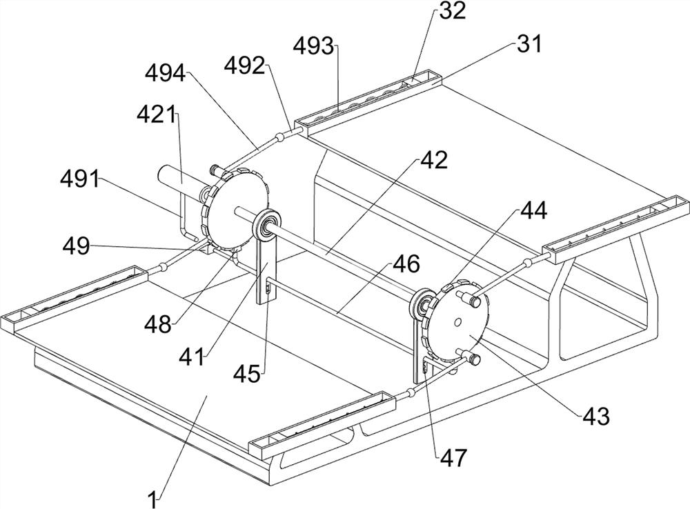
[0033] On the basis of Example 1, such as figure 1 with Figure 4 As shown, a distance adjustment assembly 4 is also included, and the distance adjustment assembly 4 includes a mounting block 41, a rotating shaft 42, a first handle 421, a turntable 43, a protrusion 44, a U-shaped bar 46, a second spring 47, a block 48, a second Two wedge-shaped blocks 49, L-shaped bar 491, pull bar 492, the 3rd spring 493 and connecting rod 494, two parts before and after the mounting base 1 are all provided with mounting block 41, and the rotating type is provided with rotating shaft 42 between front and back two mounting block 41 tops , the rear part of the rotating shaft 42 is slidingly provided with a first handle 421, the front and rear parts of the rotating shaft 42 are provided with a turntable 43, the periphery of the turntable 43 is provided with a circle of protrusions 44, and the lower part of the mounting block 41 has a word hole 45, two words Sliding between the holes 45 is provi...


PUM


Abstract

The invention relates to a detection device, in particular to a glass impact type detection device in intelligent manufacturing. The glass impact type detection device in intelligent manufacturing canautomatically detect glass, and is accurate in detection result and high in working efficiency. A glass impact type detection device in intelligent manufacturing comprises a mounting base; an impactassembly which is mounted on the mounting base and impacts in a sliding manner; and a placement assembly which is mounted on the mounting base. Glass can be knocked and detected through the impact assembly instead of manpower, a large amount of manpower is saved, the working efficiency of people is improved, the glass needing to be detected can be placed through the placement assembly, meanwhile,the impact force borne by the glass during impact detection can be adjusted, the distance between the glass and an impact block can be more accurately adjusted through a distance adjusting assembly according to the requirements of people, and the glass needing to be detected can be supported through a supporting assembly.

Description

technical field [0001] The invention relates to a detection device, in particular to a glass impact detection device in intelligent manufacturing. Background technique [0002] Glass is a hard and brittle transparent object without a certain melting point. It is generally made by mixing quartz sand, limestone, soda ash, etc., melting, molding, and cooling at high temperature. After the glass is manufactured, it is necessary to inspect the manufactured glass. [0003] At present, the glass is generally detected by manually tapping the glass with tools. This manual tapping method requires a lot of manpower. The manual tapping method has inconsistent tapping strength, which may easily lead to detection. The result is imprecise and the work efficiency is low. [0004] Therefore, it is necessary to invent a glass impact detection device in intelligent manufacturing that can automatically detect glass, with accurate detection results and high work efficiency to solve the above p...

Claims


Application Information

Patent Timeline
Patent Type & Authority Applications(China)
IPC IPC(8): G01N3/307G01N3/02
CPCG01N3/02G01N3/307G01N2203/0035
Inventor 王丹
Owner 广州幸永科技有限公司
Learn More