Loading test device and method for crack load transfer behavior of road material
A technology for loading test devices and material cracks, which is applied in the direction of applying repetitive force/pulsation force to test the strength of materials, etc., to achieve the effects of convenient disassembly, convenient operation and low cost
Pending Publication Date: 2021-02-09
SHENYANG JIANZHU UNIVERSITY
View PDF6 Cites 0 Cited by
- Summary
- Abstract
- Description
- Claims
- Application Information
AI Technical Summary
Problems solved by technology
At present, there is no special test tool and test device in the test of the mechanical attenuation of the cracked road material in the road engineering under different loads and crack widths. Therefore, there is an urgent need for a convenient road material loading test. , The loading balance
Method used
View moreImage
Smart ImageViewing Examples
Examples
 PUM
 Abstract
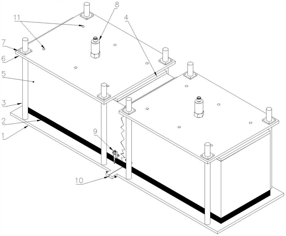
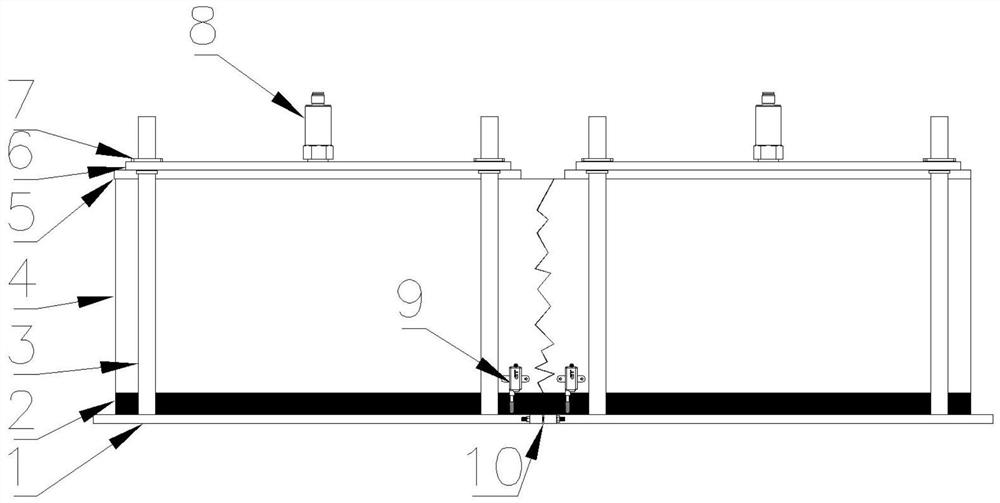
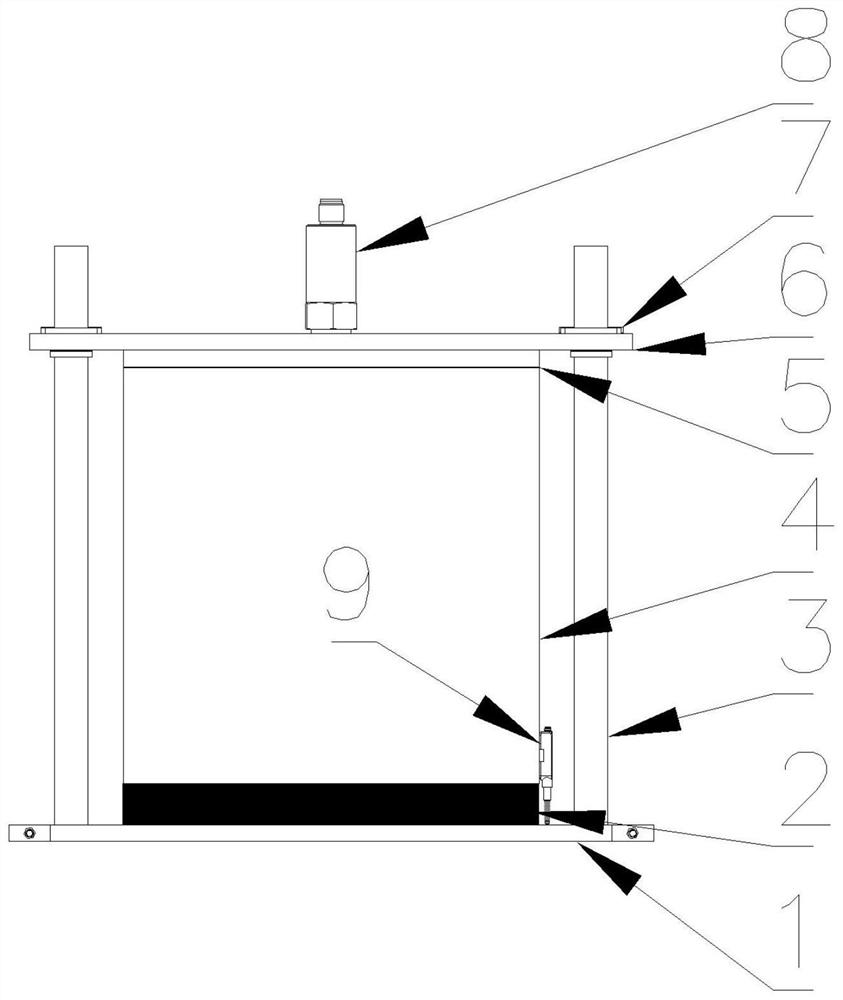
The invention relates to a pavement material crack load transfer behavior loading test device and method. The device comprises two loading units which are symmetrically arranged, and a prefabricated crack is arranged between the two loading units; each loading unit comprises a bottom support plate, the bottom support plates of the two loading units are connected through a bolt, and a steel sheet is arranged between the bottom support plates; chloroprene rubber is arranged on the bottom support plate, a road material test piece, a small bonding control plate and a large stable loading plate aresequentially arranged on the chloroprene rubber, and stable control rods are arranged between the large stable loading plate and the bottom support plate and located at the four corners of the loading unit; a testing machine actuating head is arranged at the upper part of the large stable loading plate; displacement sensors are symmetrically adhered to the side surfaces of the road material testpiece on the two sides of the prefabricated crack. Under the action of a reciprocating load, dynamic load loading under the condition of mechanical attenuation is achieved under different crack widths, integrity and stability are achieved, and the complete and stable load transmission process can be achieved.
Description
technical field [0001] The invention belongs to the technical field of crack load transfer of road materials for road engineering, and in particular relates to a loading test device and method for crack load transfer behavior of road materials. Background technique [0002] Most of the pavement structure of high-grade highways in my country adopts the form of semi-rigid base asphalt pavement, and transverse cracking is a common disease form of semi-rigid base asphalt pavement, which occurs in large numbers in the early stage of pavement service. sewing work status. As the number of driving loads increases, the load-transmitting capacity of the joints will gradually weaken. Coupled with reasons such as poor design and construction control, natural disasters or structural aging, the crack area will continue to be damaged. Therefore, it is of great significance to the safety assessment of road engineering to explore the crack propagation mechanism and law of road material struc...
Claims
Login to View More Application Information
Patent Timeline
 IPC IPC(8): G01N3/32
CPCG01N3/32
Inventor 张怀志张帅赵天颂赵寻杨海龙邓应林
Owner SHENYANG JIANZHU UNIVERSITY
Features
- R&D
- Intellectual Property
- Life Sciences
- Materials
- Tech Scout
- Unparalleled Data Quality
- Higher Quality Content
- 60% Fewer Hallucinations
Learn More Browse by: Latest US Patents, China's latest patents, Technical Efficacy Thesaurus, Application Domain, Technology Topic, Popular Technical Reports.
© 2025 PatSnap. All rights reserved.Legal|Privacy policy|Modern Slavery Act Transparency Statement|Sitemap|About US| Contact US: help@patsnap.com


