Connecting structure

A technology of connection structure and connection base, which is applied in the direction of television, optics, instruments, etc., can solve the problems of inability to adjust the relative angle of the lens and the camera, complicated operation, etc., and achieve the effect of realizing the relative angle change and simple and convenient operation.

Pending Publication Date: 2021-02-09
舜宇光学(中山)有限公司
View PDF0 Cites 0 Cited by
  • Summary
  • Abstract
  • Description
  • Claims
  • Application Information

AI Technical Summary

Problems solved by technology

[0004] The purpose of the present invention is to solve the above problems, provide a connection structure for connecting the lens and the camera, and solve the problem that ...

Method used


Image

  • Connecting structure
  • Connecting structure
  • Connecting structure

Examples


Embodiment approach

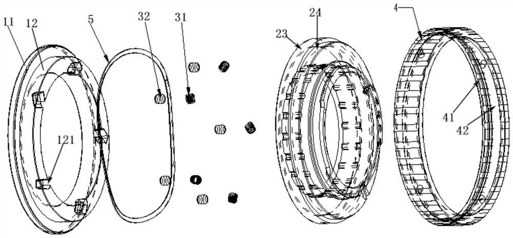
[0032] According to the second embodiment of the present invention, the installation groove 121 extends along a direction having an oblique angle with the radial direction of the second part 12 . For example, as shown in the figure, according to an embodiment of the present invention, the mounting groove 121 and the second portion 12 have a counterclockwise deflection angle in the radial direction. Such setting, in addition to ensuring that the relative angle between the connecting base 1 and the interface piece 2 is not easy to change due to accidental collision or vibration, etc., is also conducive to more conveniently realizing the relative angle adjustment between the connecting base 1 and the interface piece 2 . The reason is that the direction of the installation groove 121 has an included angle with the radial direction, and the self-acting force of the elastic limiter 121 is consistent with the direction of the installation groove 121, so it is more convenient to realiz...


PUM


Abstract

The invention relates to a connecting structure which comprises a connecting base (1) and an interface piece (2) rotationally connected with the connecting base (1), the connecting base (1) comprisesa first part (11) and a second part (12) which are connected in sequence, a plurality of mounting grooves (121) are formed in the inner wall of the second part (12) in the circumferential direction, and elastic limiting pieces (3) are mounted in the mounting grooves (121). A plurality of limiting grooves (21) matched with the elastic limiting pieces (3) are formed in the interface piece (2). The invention relates to a connecting structure, which can realize adjustment of a relative angle between a lens and a camera after the lens and the camera are connected, and is simple and convenient to operate.

Description

technical field [0001] The invention relates to the field of optical device design, in particular to a connection structure for connecting a lens and a camera. Background technique [0002] With the development of digital electronic technology, the market demand for various lens applications is becoming more and more extensive, especially in security monitoring, intelligent transportation, industrial automation and other technical fields. [0003] The interface part of the lens is the core structure that connects the lens and the camera. The common interface structures in the current market include threaded interfaces such as C interface and CS interface; there are bayonet type interfaces such as E bayonet and F bayonet; Tighten the interface, etc. The disadvantage of the threaded interface is that after the lens is assembled on the camera, the angle of the lens relative to the camera is random; after the bayonet type interface lens is assembled on the camera, it is not eas...

Claims


Application Information

Patent Timeline
IPC IPC(8): G03B17/14H04N5/225
CPCG03B17/14H04N23/55
Inventor 董文飞李玉成
Owner 舜宇光学(中山)有限公司
Why Eureka
Try Eureka