Cable fixing device
A cable fixing device and fixing device technology, applied in the direction of electrical components, etc., can solve problems such as cable sliding, and achieve the effect of being easy to use, simple to operate, and solving installation and fixing problems.
- Summary
- Abstract
- Description
- Claims
- Application Information
AI Technical Summary
Problems solved by technology
Method used
Image
Examples
Embodiment 1
[0051] Embodiment 1: It is used for long-term fixing of cables.
[0052] 1. Use the cable assembly to bundle the cables;
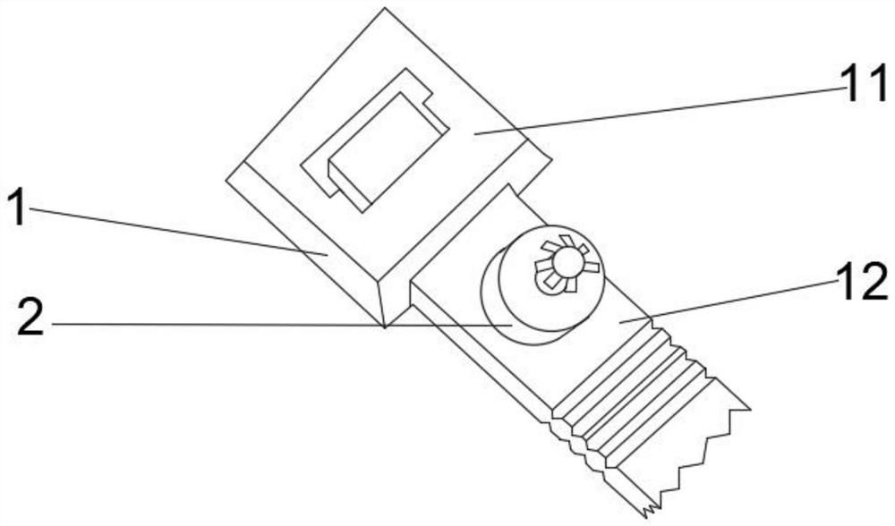
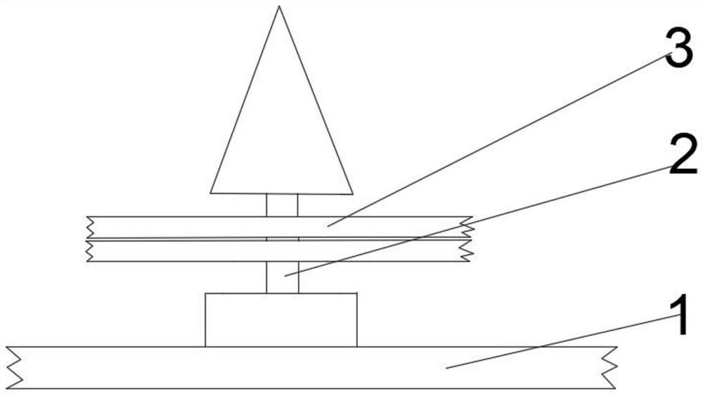
[0053] 2. Use the fixing component 3 containing the first adhesive part 31, install the two fixing components 3 on the connection component 2, and keep the first adhesive part 31 away from the cable; rotate the two fixing components 3 to an appropriate angle, preferably , the two fixing components 3 and the cable are at 60 degrees to each other.
[0054] 3. Tear off the release paper on the two fixing components 3, and according to the actual situation, bend the two fixing components 3 so that the two fixing components 3 have as much contact area as possible with the surface to be pasted, and stick them to a suitable position.
[0055] 4. (Optional) Use the screw holes on the two fixing components 3 to further fix with screws.
Embodiment 2
[0056] Embodiment 2: It is used to temporarily fix cables on metal.
[0057] 1. Use the cable assembly to bundle the cables;
[0058] 2. Using the fixing component 3 including the second adhesive part 34, install a fixing component 3 on the connection component 2; rotate the fixing component 3 to form an appropriate angle, preferably, the fixing component 3 is perpendicular to the cable.
[0059] 3. According to the actual situation, bend the fixing component 3 so that the fixing component 3 is magnetically pasted on the metal.
[0060] 4. (Optional) Use the screw holes on the fixing component 3 to further fix it with screws.
[0061] The cable fixing device designed by the invention solves the cable fixing problem, is easy to use, simple to operate, and easy to manufacture in batches in industry.
Embodiment 3
[0062] Embodiment 3: It is used to fix the cable on the thin columnar object.
[0063] 1. Use the cable assembly to bundle the cables;
[0064] 2. Install a fixing component 3 on the connection component 2; rotate the fixing component 3 to form a suitable angle, preferably, the fixing component 3 is perpendicular to the cable.
[0065] 3. Bend the fixing component 3 so that the fixing component 3 surrounds the thin columnar object, and make the first adhesion part 31 or the second adhesion part 34 on both sides of the fixing component 3 close to each other; if the fixing component 3 including the first adhesion part 31 is used , then tear off the release paper, so that the first adhesive parts 31 on both sides are bonded; if the fixing assembly 3 including the second adhesive part 32 is used, the second adhesive parts 34 on both sides will attract each other due to magnetic reasons.
[0066] 4. (Optional) Use cables to pass through the screw holes at both ends of the fixing c...
PUM
 Abstract
Description
Claims
Application Information
 - R&D
- Intellectual Property
- Life Sciences
- Materials
- Tech Scout
- Unparalleled Data Quality
- Higher Quality Content
- 60% Fewer Hallucinations
Browse by: Latest US Patents, China's latest patents, Technical Efficacy Thesaurus, Application Domain, Technology Topic, Popular Technical Reports.
© 2025 PatSnap. All rights reserved.Legal|Privacy policy|Modern Slavery Act Transparency Statement|Sitemap|About US| Contact US: help@patsnap.com


