Neurological examination lifting device

A lifting device and neurology technology, applied in the field of neurology examination lifting devices, can solve the problems of inflexibility, poor comfort, inconvenient inspection, etc., and achieve the effect of flexible device

Inactive Publication Date: 2021-02-12
杭州华慧医药科技有限公司
View PDF1 Cites 0 Cited by
  • Summary
  • Abstract
  • Description
  • Claims
  • Application Information

AI Technical Summary

Problems solved by technology

[0006] The purpose of the present invention is to provide a lifting device for neurology examination in order to solve the problems of poor comfort, inconvenient follow-up examination and inflexibility in the use process of the existing device.

Method used


Image

  • Neurological examination lifting device
  • Neurological examination lifting device
  • Neurological examination lifting device

Examples


Embodiment 1

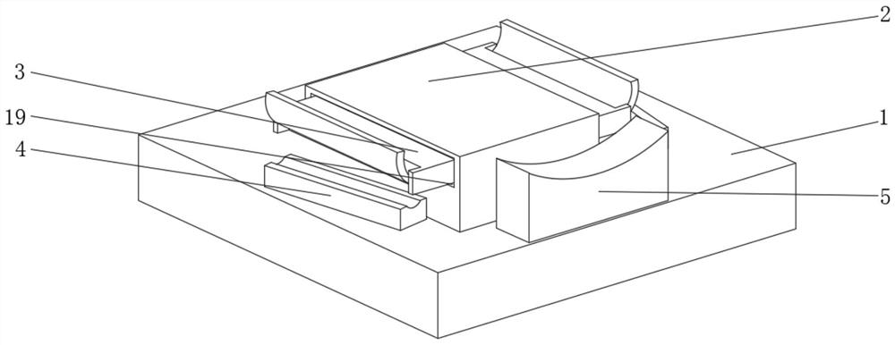
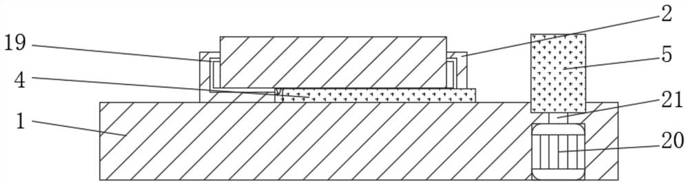
[0029] see figure 1 and 2 , a lifting device for neurology examination, comprising a support platform 1, a support frame 2 is connected to the top side of the support platform 1, an arm placement block 4 is connected to the side of the support platform 1 close to the support frame 2, and the support platform 1 is close to the arm One side of the placement block 4 is connected with a head placement block 5, and the support table 1 is fixedly connected with a motor 20 near the interior of the head placement block 5, and the output shaft of the motor 20 is fixedly connected with a second screw rod 21, and the two sides of the support frame 2 Connected to the limiting device 3 , slide grooves 19 are provided on both sides of the support frame 2 close to the limiting device 3 .

[0030] In this embodiment, through the cooperation of the motor 20 installed inside the device and the second screw rod 21, the device can flexibly change the height of the head placement block 5, making ...

Embodiment 2

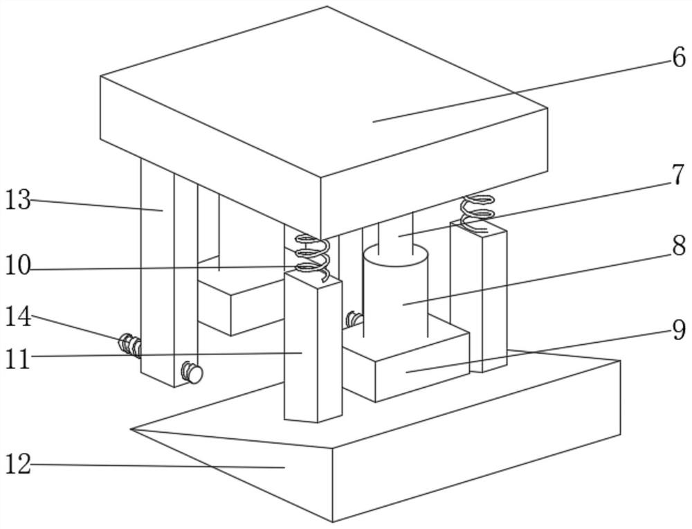
[0032] see image 3 , this embodiment is further optimized on the basis of Embodiment 1, specifically, the bottom end of the support frame 2 is fixedly connected with a connecting block 6, and one side of the bottom end of the connecting block 6 is fixedly connected with a connecting column 7. The end of the column 7 away from the connecting block 6 is connected with a hollow sleeve 8 , and the end of the hollow sleeve 8 away from the connecting column 7 is fixedly connected with a limiting block 9 .

[0033] Specifically, a rectangular groove is opened inside the supporting platform 1 , and the supporting platform 1 is slidably connected with the limiting block 9 .

[0034] Specifically, the side of the connection block 6 close to the connection column 7 is fixedly connected with a spring 10, and the side of the connection block 6 away from the spring 10 is fixedly connected with a support column 13. The bottom end of the rod 11 is connected with a slope 12 .

[0035] Speci...

Embodiment 3

[0038] see image 3 and 4 , the present embodiment is optimized as follows on the basis of example 1 or example 2, specifically, the inside of the limiting device 3 is connected with a drive block 15, and the side of the drive block 15 away from the support frame 2 is rotatably connected with a rotating shaft 22, The handle 17 is fixedly connected to the center of the rotating shaft 22 , and the force receiving gear 18 is fixedly connected to the side of the rotating shaft 22 close to the handle 17 .

[0039] Specifically, a motor is fixedly connected to the inside of the drive block 15 , and a drive gear 23 is fixedly connected to the output shaft of the motor, and the drive gear 23 is meshed with the force receiving gear 18 .

[0040] Specifically, a screw hole 16 is opened inside the end of the drive block 15 away from the handle 17 , and the drive block 15 is screwed to the support frame 2 .

[0041] In this embodiment, through the limiting device 3 installed inside the ...


PUM


Abstract

The invention discloses a neurological examination lifting device and relates to the technical field of medical instruments. The neurological examination lifting device comprises a supporting table, wherein a supporting frame is connected to one side of the top end of the supporting table, an arm placing block is connected to one side, close to the supporting frame, of the supporting table, and ahead placing block is connected to one side, close to the arm placing block, of the supporting table; and a motor is fixedly connected to the interior, close to the head containing block, of the supporting table, and a second screw is fixedly connected to an output shaft of the motor. According to the device, through the cooperation effect of a motor and a second screw installed in the device, thedevice can flexibly change the height of a head containing block, the device is more comfortable to use, and through a supporting frame installed in the device, after the device is lifted to a certain position, through the effect of a sliding rod and a slope, the height of the head containing block can be adjusted; and the angle of the supporting frame is changed so that the device is more convenient during subsequent operation.

Description

technical field [0001] The invention relates to the technical field of medical devices, and more specifically relates to a lifting device for neurology examination. Background technique [0002] At present, in neurology clinical practice, for patients who are not sensitive to local nerve atrophy or local nerve stimulation, medical staff need to check the affected area, sometimes requiring the patient to raise the upper or lower limbs, but most patients have inconvenient limb movements and cannot move freely. Medical personnel are required to assist and cooperate, so that both medical personnel and patients feel very tired, and it is also inconvenient to perform inspection operations. [0003] In Chinese Patent Application No. CN201720691679.2, there is disclosed a lifting device for neurology examination, including a neurology examination bed, a support frame, a movable frame and a disposable sterile arm cover, characterized in that the neurology examination bed There are s...

Claims


Application Information

Patent Timeline
IPC IPC(8): A61G13/12A61G13/10A61G13/02
CPCA61G13/02A61G13/10A61G13/12A61G13/121A61G13/1235A61G13/1245
Inventor 陈威
Owner 杭州华慧医药科技有限公司
Why Eureka
Try Eureka