Transversely-moving type dispensing device for electronic components
What is Al technical title?
Al technical title is built by PatSnap Al team. It summarizes the technical point description of the patent document.
A technology for electronic components and glue dispensing devices, which is applied to devices that apply liquid to the surface, coatings, etc. Unable to control the dispensing volume and other problems
Inactive Publication Date: 2021-02-12
江苏开创检测技术有限公司
View PDF9 Cites 0 Cited by
Summary
Abstract
Description
Claims
Application Information
AI Technical Summary
This helps you quickly interpret patents by identifying the three key elements:
Problems solved by technology
Method used
Benefits of technology
Problems solved by technology
[0002] Electronic components are components of electronic components and small electrical machines and instruments. They are often composed of several parts and can be used in similar products; they often refer to certain parts in industries such as electrical appliances, radios, and instruments, such as capacitors and transistors. Electronic components include: resistors, capacitors, potentiometers, electron tubes, radiators, electromechanical components, connectors, semiconductor discrete devices, electroacoustic devices, laser devices, electronic display devices, optoelectronics Devices, sensors, power supplies, switches, micro motors, electronic transformers, relays, printed circuit boards, integrated circuits, various circuits, piezoelectric, crystals, quartz, ceramic magnetic materials, substrate substrates for printed circuits, etc.; but now Some dispensing devices cannot control the volume of dispensing, and cannot adjust different dispensing volumes for different electronic components. In addition, the lateral position of dispensing cannot be adjusted casually.
Method used
Image
Click on the blue label to locate the original text in one second.
Reading with bidirectional positioning of images and text.
Examples
Embodiment Construction
[0021] The content of the present invention will be further described in detail below in conjunction with the accompanying drawings.
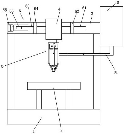
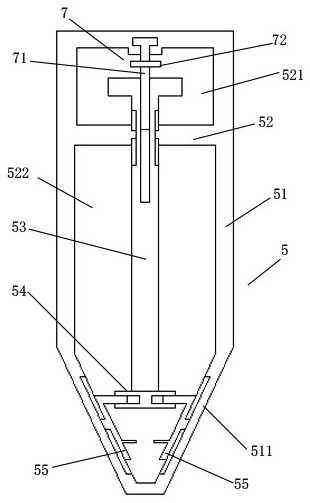
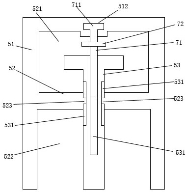
[0022] Such as Figures 1 to 5 As shown, a laterally mobile dispensing device for electronic components includes a base 1, a conveying device 2, a positioning plate 3, a telescoping mechanism 4, a dispensing mechanism 5, and a lateral driving mechanism 6; the upper end of the base 1 is equipped with a conveying device 2; a positioning plate 3 is installed above the base 1; a telescopic mechanism 4 is installed in the middle of the positioning plate 3; a dispensing mechanism 5 is installed at the lower end of the telescopic mechanism 4; the dispensing mechanism 5 includes a glue storage cylinder 51, Partition plate 52, floating rod 53, connecting plate 54, sliding plate 55, driving cross bar 57, rubber control plate 56; partition plate 52 is installed above the interior of the rubber storage cylinder 51; the upper end of the partition plate 52 i...
PUM
Abstract
The invention discloses a transversely-moving type dispensing device for electronic components. The transversely-moving type dispensing device comprises a base, a conveying device, a positioning plate, a telescopic mechanism, a dispensing mechanism and a transverse driving mechanism. According to the transversely-moving type dispensing device for the electronic components, a driving internal threaded cylinder rotates and drives a transverse moving screw rod to move on a penetrating and connecting plate in a penetrating and connecting mode, so that the telescopic mechanism is driven to move transversely, the telescopic mechanism is connected to a guide plate in a sliding and penetrating-connecting mode through a guide rod on one side, transverse moving stability is achieved, therefore it can be guaranteed that the dispensing mechanism stably and transversely moves, and the adjustment of the transverse dispensing position is realized.
Description
technical field [0001] The invention relates to a laterally moving dispensing device for electronic components. Background technique [0002] Electronic components are components of electronic components and small electrical machines and instruments. They are often composed of several parts and can be used in similar products; they often refer to certain parts in industries such as electrical appliances, radios, and instruments, such as capacitors and transistors. Electronic components include: resistors, capacitors, potentiometers, electron tubes, radiators, electromechanical components, connectors, semiconductor discrete devices, electroacoustic devices, laser devices, electronic display devices, optoelectronics Devices, sensors, power supplies, switches, micro motors, electronic transformers, relays, printed circuit boards, integrated circuits, various circuits, piezoelectric, crystals, quartz, ceramic magnetic materials, substrate substrates for printed circuits, etc.; b...
Claims
Application Information
Patent Timeline
Application Date:The date an application was filed.
Publication Date:The date a patent or application was officially published.
First Publication Date:The earliest publication date of a patent with the same application number.
Issue Date:Publication date of the patent grant document.
PCT Entry Date:The Entry date of PCT National Phase.
Estimated Expiry Date:The statutory expiry date of a patent right according to the Patent Law, and it is the longest term of protection that the patent right can achieve without the termination of the patent right due to other reasons(Term extension factor has been taken into account ).
Invalid Date:Actual expiry date is based on effective date or publication date of legal transaction data of invalid patent.