Tower type cyclone flow test device for converting axial compression into radial sealing

A technology of radial sealing and flow testing, which is applied in the direction of measuring devices, engine testing, and engine sealing, etc. It can solve problems such as the influence of reliability of test results, difficulty in stabilizing test data, and affecting test efficiency, so as to improve the accuracy of test results , reliable results, avoid interference effect

Active Publication Date: 2021-02-12
中国船舶重工集团公司第七0三研究所
View PDF5 Cites 3 Cited by
  • Summary
  • Abstract
  • Description
  • Claims
  • Application Information

AI Technical Summary

Problems solved by technology

However, due to the particularity of the structure of the tower cyclone, it does not have a large enough installation end face in the axial direction for clamping and fixing, and as gas turbines are moving towards smaller size, lighter weight, higher power and lower emissions In the direction of development, the size of the non-essential axial installation end face of the tower cyclone becomes smaller during the optimization process, and the end face is usually cast and rough, which makes the sealing more difficult during the flow test, and the outlet The air flow often causes detection interference to the test sealing position, and the reliability of the test results is affected
In addition, due to structural reasons, the test data is not easy to stabilize, and the adjustment takes a long time, which affects the test efficiency

Method used


Image

  • Tower type cyclone flow test device for converting axial compression into radial sealing
  • Tower type cyclone flow test device for converting axial compression into radial sealing
  • Tower type cyclone flow test device for converting axial compression into radial sealing

Examples


Embodiment Construction

[0016] The present invention is described in more detail below in conjunction with accompanying drawing example:

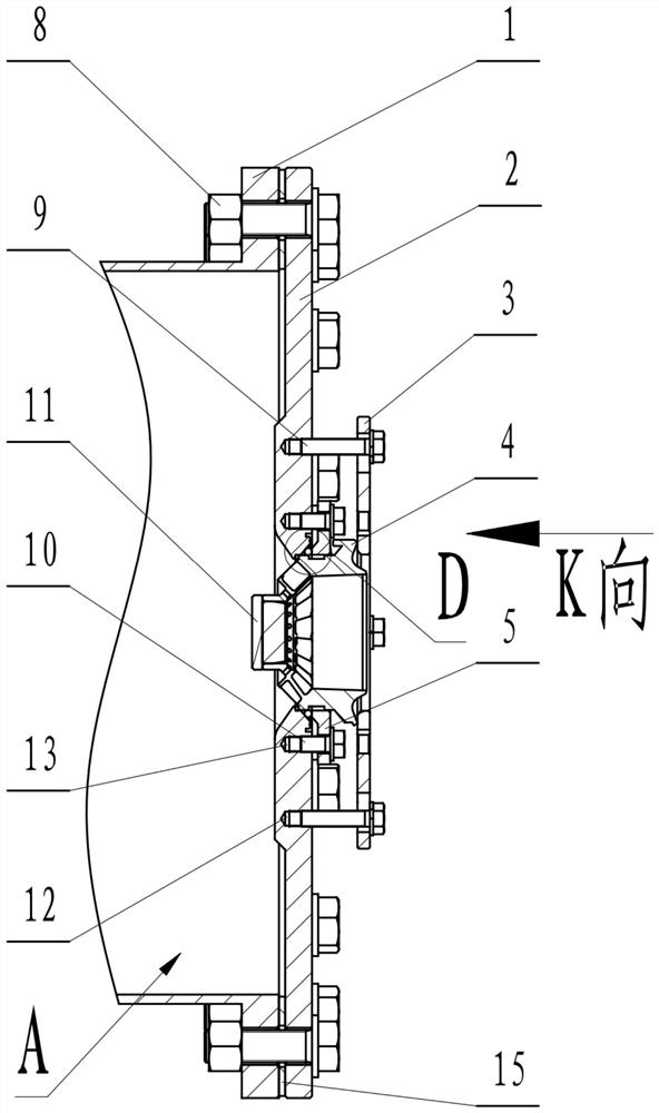
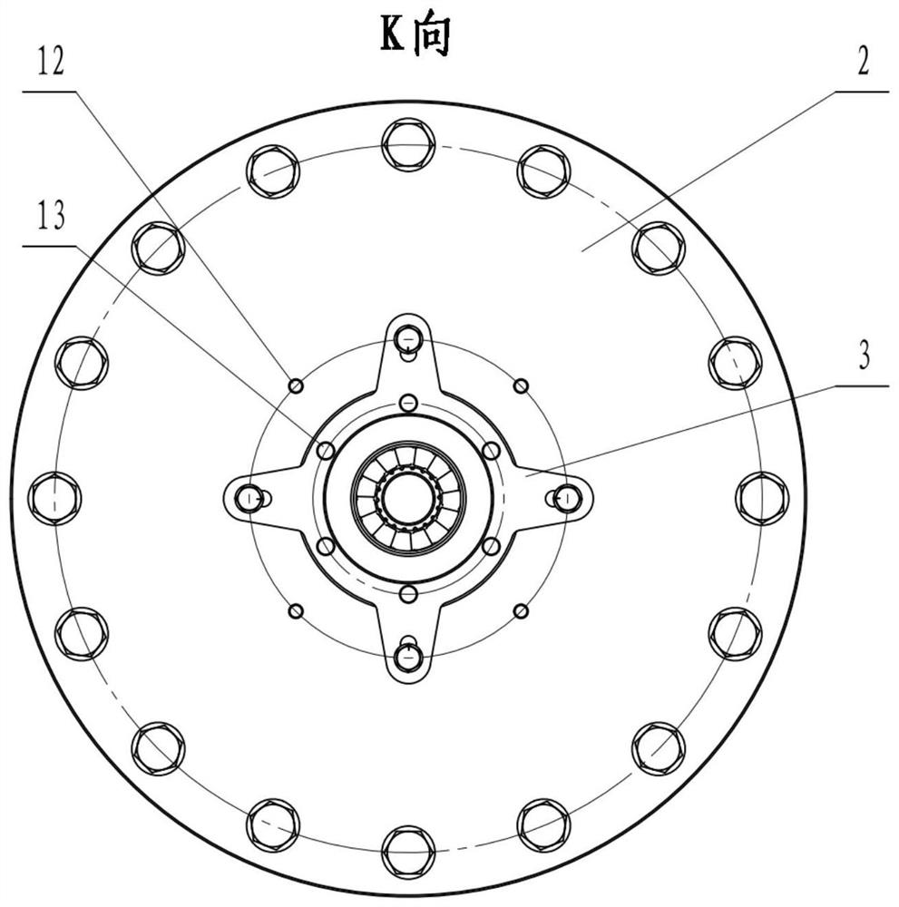
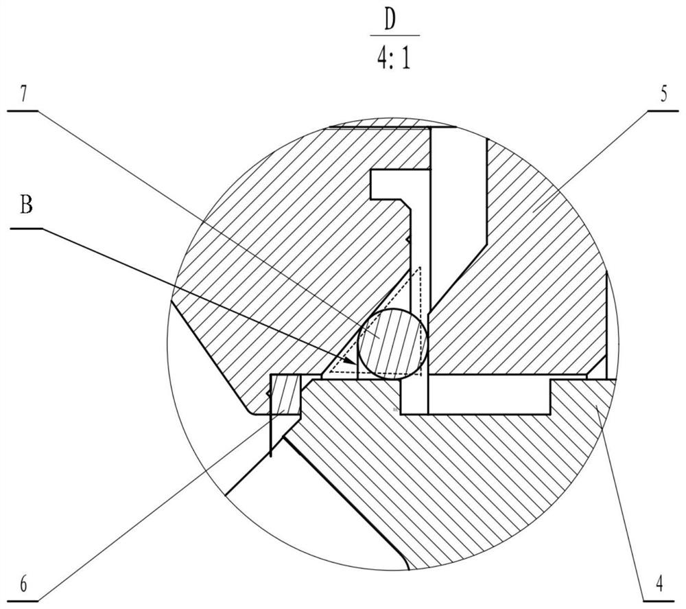
[0017] combine Figure 1-3 , mainly including supporting components, pressing components and sealing components.

[0018] Such as figure 1 As shown, the support assembly mainly includes a pressure-stabilizing cylinder 1, a convex-concave cover plate 2, a fastener 8, and a sealing ring 15, wherein the pressure-stabilizing cylinder 1 buffers the incoming air through a large-volume inner chamber A to reduce the gas flow rate, so that the The incoming air pressure obtained from the test air source is more stable, thereby reducing the difficulty of pressure regulation and improving the accuracy of the test results; the convex-concave cover plate 2 adopts the design of a central opening and a convex step on one side and a concave cavity on the other. The central opening can ensure that the cyclone is sufficient The flow installation space can be adjusted according to ...


PUM


Abstract

The invention aims to provide a tower-type cyclone flow test device for converting axial compression into radial sealing. The device comprises a pressure stabilizing cylinder, a convex-concave cover plate and a cross-shaped pressing plate, the pressure stabilizing cylinder and the convex-concave cover plate are fixed together through a fastener, the convex-concave cover plate adopts a convex stepon the inner cavity surface, and adopts a stepped design on the outer cavity surface. A center hole is formed in the center of the convex-concave cover plate, a conical-column-shaped rubber plug and atower-type cyclone are arranged in the center hole, the axial position of the tower-type cyclone is fixed through a small flat end face of a step, the convex step and the edge of the center hole adopt an air inlet angle in smooth transition, a cross pressing plate is fixed to the convex-concave cover plate, and a hole is formed in the middle of the cross pressing plate. And the middle part of thetower-type cyclone is arranged in a hole in the middle part of the cross pressing plate. An O-shaped ring is compact and reliable in sealing in the formed triangular annular belt space, axial pressing is converted into radial sealing, and the problem that a flow test is difficult to seal due to the fact that the unnecessary axial installation end face of a current tower type cyclone becomes smaller and smaller is effectively solved.

Description

technical field [0001] The invention relates to a test device for a gas turbine, in particular to a test device for a combustion chamber. Background technique [0002] In the fields of gas turbines and aero-engines, tower swirlers are widely used in combustion chambers. By using tower swirlers, high-pressure air can form a strong recirculation zone at its outlet, so that the combusted gas flame can continuously flow back to ignite new ones. The mixture of air and fuel keeps the flame stable. Moreover, the length of the flame can be effectively shortened by the swirling flow, thereby reducing the axial dimension of the combustion chamber, ensuring combustion efficiency while saving space, thereby reducing the size of the entire combustion chamber. [0003] In recent years, with the improvement of gas turbine emission requirements, tower cyclones play a more crucial role in controlling air distribution, ensuring lean combustion, and optimizing flow fields. In order to ensure...

Claims


Application Information

Patent Timeline
Patent Type & Authority Applications(China)
IPC IPC(8): G01M15/14G01M15/02F16J15/10
CPCG01M15/14G01M15/02F16J15/104F16J15/10
Inventor 林枫齐秀龙李名家李雅军冉军辉程旭王俊
Owner 中国船舶重工集团公司第七0三研究所
Why Eureka
Try Eureka