Electrorheological fluid flow mode rheological property test device

A technology of electrorheological fluid and flow mode, applied in the direction of measuring devices, flow characteristics, instruments, etc., can solve the problems of inaccurate results, inability to measure high shear rate of electrorheological fluid, inaccurate test results, etc., and achieve liquid volume utilization High efficiency, solving sealing difficulties, and simple structure

Active Publication Date: 2022-03-15
HEFEI UNIV OF TECH
View PDF11 Cites 0 Cited by
  • Summary
  • Abstract
  • Description
  • Claims
  • Application Information

AI Technical Summary

Problems solved by technology

In the shear mode, the electrorheological fluid will be affected by centrifugation, and the measured results are not accurate, which means that the current testing technology is actually unable to measure the high shear rate of the electrorheological fluid
Although the measuring device for rheological properties of the plate type electrorheological fluid can avoid the influence of centrifugation on the experimental results, its working mode is still the shear mode; the working mode of the measuring device for the rheological properties of the plunger type electrorheological fluid is flow mode and shear mode. Mode mixing; although the working mode of the cylinder-type electrorheological fluid rheological property measuring device is the flow mode, it is the same as the plunger-type electrorheological fluid measuring device, only part of the electrorheological fluid is placed in the electric field, and there are suspended particles in the electrorheological fluid Aggregation and mother liquor outflow accumulation phenomenon, resulting in inaccurate test results

Method used


Image

  • Electrorheological fluid flow mode rheological property test device
  • Electrorheological fluid flow mode rheological property test device
  • Electrorheological fluid flow mode rheological property test device

Examples


Embodiment Construction

[0028] Next, an embodiment of the present invention will be described in detail, and the present embodiment is implemented in the preparation of the present invention, the detailed embodiment and the specific operation process are given, but the scope of protection of the present invention is not limited to the implementation below. example.

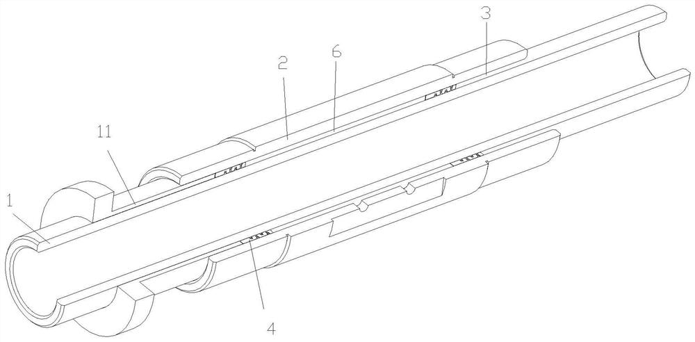
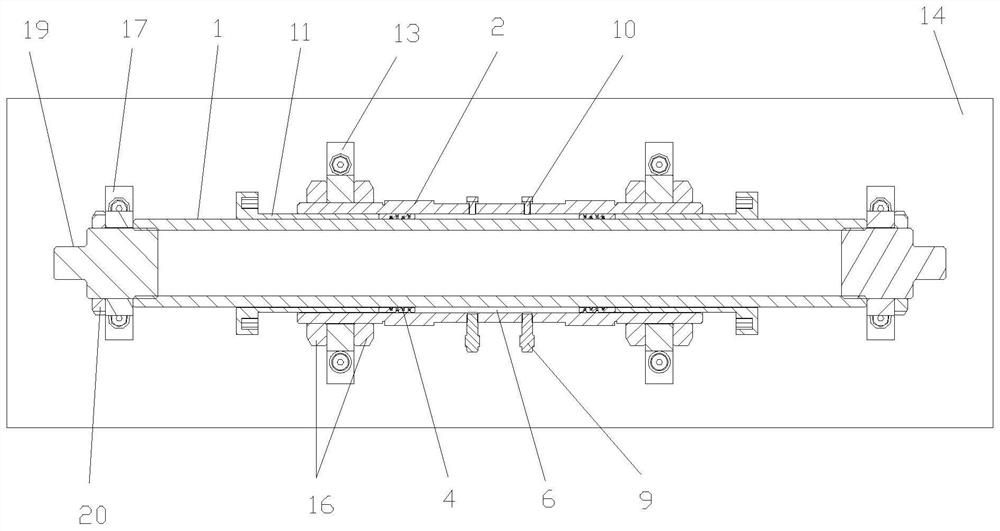
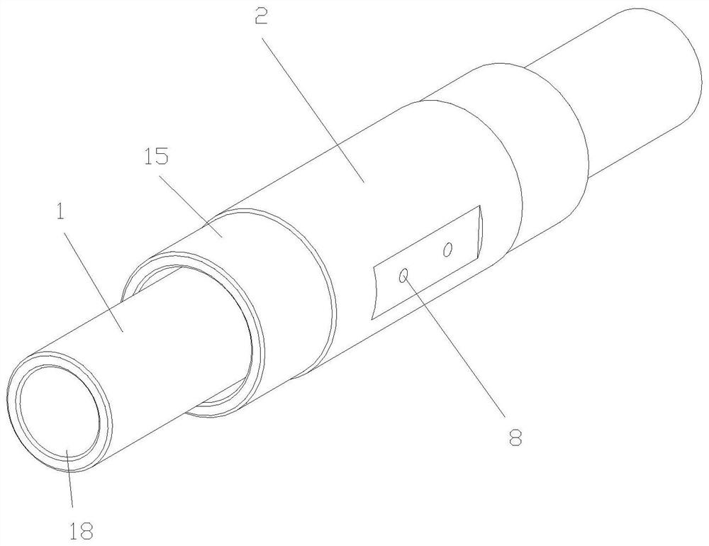
[0029] See Figure 1 to 9 , The present embodiment discloses electrorheological fluids flow pattern rheological properties testing device, comprising an anode electrode arranged coaxially inside and outside the cylinder along the cylinder 12 and the cathode electrode, anode electrode tube 1 ends are cylinder 2 protrudes out of the cathode electrode both ends of the outside. An anode electrode formed cylindrical annular gap and the gap between the cathode electrode 2 cylinder 3, an annular gap 3 equipped with two annular piston 4, opposite ends of each piston 4 abutting annular sealing an annular gap between the inner and outer walls 3, the an...


PUM


Abstract

The invention discloses a device for testing the rheological properties of the electrorheological fluid flow mode, which includes an anode electrode cylinder and a cathode electrode cylinder arranged coaxially inside and outside, the gap between the anode electrode cylinder and the cathode electrode cylinder forms an annular gap, two annular pistons and The inner and outer walls of the annular gap together form a housing chamber for containing the electrorheological fluid. Under the action of the driving mechanism, the two annular pistons can move back and forth synchronously in the annular gap, thereby driving the electrorheological fluid in the housing chamber to synchronize Move; the radial uniform electric field generated after the anode electrode cylinder and the cathode electrode cylinder are connected to the external power supply can pass through the entire annular gap vertically; there are two sensor mounting holes and at least one exhaust bolt hole on the outside of the cathode electrode cylinder, and the two Pressure sensors are respectively installed at the sensor mounting holes, and exhaust bolts are installed at the exhaust bolt holes. The present invention has the advantages of providing a rheological property test scheme under the flow mode of the electrorheological fluid, and ensuring the accuracy of the test.

Description

Technical field [0001] The present invention relates to the field current of the rheological properties of test fluids, in particular, it relates to an electrorheological fluid flow pattern rheological properties testing means. Background technique [0002] ER fluid is a controllable smart material, a mixture of a liquid dielectric and the insulating particles made. Having good flowability in the absence of electric field, as a low viscosity Newtonian fluid; external electric field, solid particles in the ER fluid induced by the electric field, showing a high viscosity, low flow characteristics of a Bingham body. ER fluids have been used in vibration control, mechanical transmission, automation and other fields. [0003] Shear yield stress and the response time measured electrorheological fluid properties is important to the design and method of controlling the current varying device. Electrorheological fluid having three different operating modes, namely, the flow mode, shear mo...

Claims


Application Information

Patent Timeline
Patent Type & Authority Patents(China)
IPC IPC(8): G01N11/00
CPCG01N11/00
Inventor 祝安定何冠男白先旭
Owner HEFEI UNIV OF TECH
Why Eureka
Try Eureka