Conductive composite diaphragm suitable for deposition type slurry battery

A slurry battery and composite diaphragm technology, which is applied to battery pack parts, circuits, electrical components, etc., can solve the problems of easy to pierce the isolation layer, reduce the service life of the battery, improve the clogging of the diaphragm, and improve the volume utilization rate , prevent puncture, improve the effect of safety performance

Inactive Publication Date: 2018-12-21
CENT SOUTH UNIV
View PDF3 Cites 4 Cited by
  • Summary
  • Abstract
  • Description
  • Claims
  • Application Information

AI Technical Summary

Problems solved by technology

[0004] However, it has the following disadvantages: the gap between the isolation layer and the collector layer is the highest active point of the electrochemical reaction, and the active slurry close to the collector layer moves at almost zero speed during the flow process, so the isolation layer and the collector layer The active material in the gap between the collector layers is very likely to produce dendrites, and because the generated dendrites are directly in contact with the isolation layer, the dendrites are easy to pierce the isolation layer and cause a greater safety hazard, and also improve the performance of the separator. risk of clogging and greatly reduces battery life

Method used


Image

  • Conductive composite diaphragm suitable for deposition type slurry battery

Examples


Embodiment 1

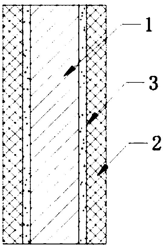
[0026] Such as figure 1 As shown, this embodiment provides a conductive composite separator suitable for deposition-type slurry batteries, which includes an isolation layer 1, a conductive layer 2 disposed on both sides of the isolation layer 1, and a conductive layer disposed on the conductive layer 2. and the insulating coating 3 between the isolation layer 1; wherein, the conductive layer 2, the insulating coating 3, the isolation layer 1, the insulating coating 3 and the conductive layer 2 are sequentially stacked and Laminated into one, the gap between two adjacent layers is not greater than 10μm.

[0027] In this embodiment, two layers of conductive layers 2 and one layer of isolation layer 1 form the conductive composite diaphragm, and the insulating coating 3 is provided between the conductive layer 2 and the isolation layer 1, so that the The side of the conductive layer 2 close to the isolation layer 1 is in a state covered by the insulating coating 3, thereby avoid...

Embodiment 2

[0040] On the basis of Example 1, this example further provides a specific preparation method for the conductive composite diaphragm suitable for fluidized batteries:

[0041] The conductive layer 2 is made of 240-mesh metal mesh, and the metal mesh is made of metal wire with a diameter of 15 μm; the conductive layer 2 contacting the positive electrode slurry is made of aluminum wire, and the conductive layer 2 contacting the negative electrode is made of aluminum wire. Layer 2 is made of copper wire; the isolation layer 1 adopts a dry stretched single-layer PP diaphragm, the porosity of the isolation layer 1 is 50%, and the thickness of the isolation layer 1 is 10 μm; the insulating coating 3. The coating is made of insulating thermoplastic polymer material;

[0042] During production, firstly, the conductive layer 2 is coated, and all parts of the conductive layer 2 except the leading end are immersed in the coating of the insulating coating 3, and then taken out to dry, so ...


PUM

PropertyMeasurementUnit
thicknessaaaaaaaaaa
thicknessaaaaaaaaaa
diameteraaaaaaaaaa

Abstract

The invention provides a conductive composite diaphragm suitable for a deposition type slurry battery, which comprises an isolation layer, a conductive layer arranged on both sides of the isolation layer, and an insulating coating arranged between the conductive layer and the isolation layer. Wherein the conductive layer, the insulating coating, the insulating layer, the insulating coating and theconductive layer are laminated and bonded together in sequence, and the gap between the adjacent two layers is not more than 10 [mu]m; A conductive composite diaphragm is formed by two conductive layers and one isolation layer, and the insulating coating is arranged between the conductive layer and the isolation layer, thereby avoiding the generation of dendrites between the conductive layer andthe isolation layer, preventing the isolation layer from being punctured, and improving the safety performance of the battery system; The conductive composite diaphragm realizes the integration of theisolation layer and the conductive layer, simplifies the battery structure of the deposition-type slurry battery, improves the internal volume utilization rate of the battery, and improves the mechanical strength and service life of the conductive composite diaphragm.

Description

technical field [0001] The invention relates to the technical field of slurry batteries, in particular to a conductive composite separator suitable for deposition-type slurry batteries. Background technique [0002] The deposition type slurry battery is a new type of energy storage system that combines the advantages of flow batteries and traditional batteries. The active material used is solid particles, which are mixed with the electrolyte to form a slurry. The form in the electrolyte is a suspension, Paste or form deposits. Deposition-type slurry batteries can realize the replacement of active materials, so the service life of battery active materials is not high. By allocating equipment costs to maintenance costs, energy storage costs can be greatly reduced. It is an ideal large-scale energy storage device. [0003] A lithium-ion flow battery is disclosed in the prior art, the positive electrode current collecting layer and the negative electrode current collecting lay...

Claims


Application Information

Patent Timeline
Patent Type & Authority Applications(China)
IPC IPC(8): H01M2/16H01M2/14H01M50/409H01M50/46
CPCH01M50/431H01M50/44H01M50/403H01M50/411H01M50/449Y02E60/10
Inventor 李新海刘越莫文彬王接喜王志兴郭华军胡启阳彭文杰颜果春
Owner CENT SOUTH UNIV
Why Eureka
Try Eureka