
Spiral winding device of strength training machine and strength training machine

A spiral winding and training machine technology, applied in the field of strength equipment, can solve the problems of affecting the training effect, the change of the exit angle of the pull rope A3, and the inability to achieve the training effect, etc.

Pending Publication Date: 2021-02-19
GUANGZHOU SHIYUAN ELECTRONICS CO LTD +1
View PDF0 Cites 5 Cited by
  • Summary
  • Abstract
  • Description
  • Claims
  • Application Information

AI Technical Summary

Problems solved by technology

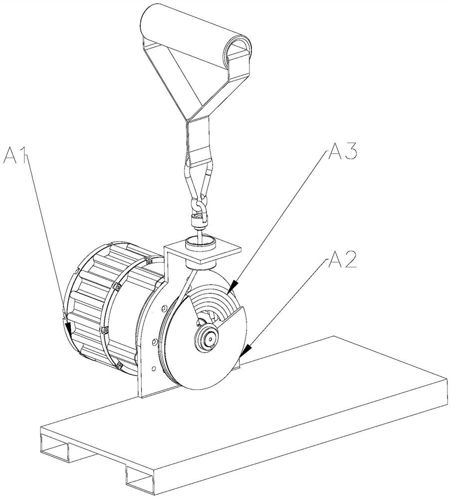
In order to obtain a larger training stroke and avoid misalignment when the pull rope A3 is retracted and retracted, such as figure 1 As shown, most of the existing strength training equipment adopts the stay cord A3 to perform single-row multi-turn winding on the reel A2. The pull radius of the rope A3 increases accordingly, and the torque increases. Since the output torque of the resistance source is constant and the torque increases, the user can overcome the output torque of the resistance source and pull the pull rope A3 with a small pulling force, which cannot achieve the desired result. training effect
In addition, the change of the pull radius of the pull rope A3 will also change the exit angle of the pull rope A3, which will affect the training effect

Method used


Image

  • Spiral winding device of strength training machine and strength training machine
  • Spiral winding device of strength training machine and strength training machine
  • Spiral winding device of strength training machine and strength training machine

Examples


Embodiment 1

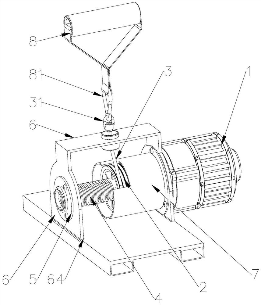
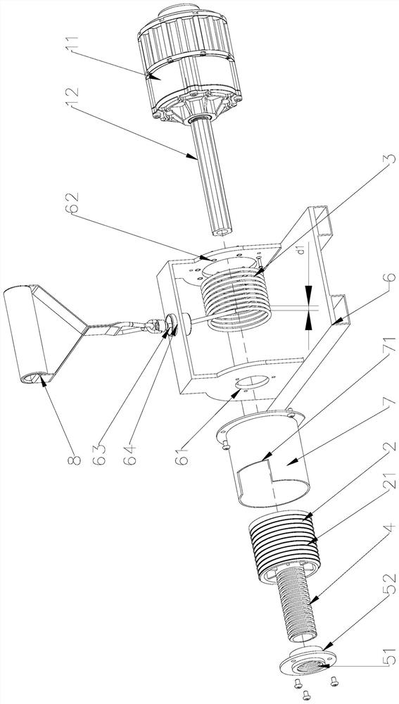
[0027] Such as figure 2 and image 3 As shown, this embodiment provides a helical winding device for a strength training machine, which includes the resistance source 1 , the winding wheel 2 , the flexible connector 3 , the screw 4 and the mounting frame 6 .

[0028] The resistance source 1 includes a resistance source body 11 and an output shaft 12 , and the resistance source 1 outputs torque through the output shaft 12 .

[0029] The reel 2 is cylindrical, and grooves 21 are provided on its side, and the grooves 21 are arranged in a spiral shape along the side of the reel 2 . One end of the flexible connecting member 3 is fixed on the reel 2 , and the flexible connecting member 3 is accommodated in the groove 21 and rotates on the reel 2 along the groove 21 one by one. One end of the reel 2 is sleeved on the output shaft 12, and the other end is fixedly connected with the screw rod 4, and the reel 2, the screw rod 4 and the output shaft 12 are coaxial.

[0030] The mount...


PUM


Abstract

The invention provides a spiral winding device of a strength training machine. The spiral winding device comprises a resistance source, a winding wheel, a flexible connecting piece, a screw rod and amounting frame; the resistance source comprises a resistance source body and an output shaft, and the resistance source can output the torque through the output shaft. The winding wheel is cylindrical, and a groove is formed in the side surface of the winding wheel and is spirally distributed along the side surface of the winding shaft; one end of the flexible connecting piece is fixed on the winding wheel, and the flexible connecting piece is accommodated in the groove and is wound on the winding wheel circle by circle along the groove; one end of the winding wheel is arranged on the output shaft in a sleeving mode, the other end of the winding wheel is fixedly connected with the screw rod, and the winding wheel, the screw rod and the output shaft are coaxial. An internal threaded hole isformed in the mounting frame, and the screw rod penetrates into the internal threaded hole to be in threaded connection with the mounting frame. Due to the fact that the moment of force of the flexible connecting piece is constant, the pulling force needing to be provided by a user is constant, and the expected training effect can be achieved.

Description

technical field [0001] The invention belongs to the field of strength equipment, and in particular relates to a spiral winding device for a strength training machine and a strength training machine. Background technique [0002] In order to miniaturize strength training equipment, many strength training equipment use motors or springs or friction wheels as resistance sources to output torque. Such as figure 1 As shown, in the existing strength training apparatus, generally include motor A1, reel A2 and pull cord A3, described reel A2 is arranged on the output shaft of described motor A1, and described stay cord A3 is wound on On the reel A2, the user pulls the pull cord A3 to overcome the output torque of the motor A1 to achieve the effect of strength training. In order to obtain a larger training stroke and avoid misalignment when the pull rope A3 is retracted and retracted, such as figure 1 As shown, most of the existing strength training equipment adopts the stay cord ...

Claims


Application Information

Patent Timeline
IPC IPC(8): A63B21/005A63B21/015A63B23/12
CPCA63B21/0058A63B21/015A63B23/12
Inventor 叶全胜
Owner GUANGZHOU SHIYUAN ELECTRONICS CO LTD
Learn More