Constant tension spring compensating unit

A spring compensation, constant tension technology, applied in the direction of overhead lines, etc., can solve the problems of inability to guarantee the constant tension of the catenary, limited use range, oil leakage, air leakage, etc., to achieve light weight, reduce offline rate, no card stagnant effect

Inactive Publication Date: 2008-07-30
帖荣俊 +4
View PDF5 Cites 12 Cited by
  • Summary
  • Abstract
  • Description
  • Claims
  • Application Information

AI Technical Summary

Problems solved by technology

[0009] 1. A compensation device composed of several cylindrical helical compression springs connected in series (for example: the elastic tension compensator with the patent number 200420025333.1; the automatic elastic tension compensator with the patent number 200510038827.2, etc.), due to the use of cylindrical helical compression The force of the spring is proportional to the stroke, and this compensation device cannot guarantee the constant tension of the catenary
[0010] 2. Adopt oil pressure and air pressure compensating devices (for example: hydraulic compensation device for electrified railway catenary with patent No. 03235102.X; differential plunger hydraulic tension compensation device with patent No. 03218606.1; electrified railway with patent No. catenary air pressure type tension automatic compensator, etc.), due to the loss of oil and gas, it needs continuous monitoring and maintenance, as well as timely replenishment of oil and gas, and oil and gas leakage sometimes occur, so the cost is high, which limits the use scope

Method used


Image

  • Constant tension spring compensating unit
  • Constant tension spring compensating unit
  • Constant tension spring compensating unit

Examples


Embodiment Construction

[0062] The constant tension spring compensating device of the present invention will be further described in detail below with reference to the drawings and specific embodiments.

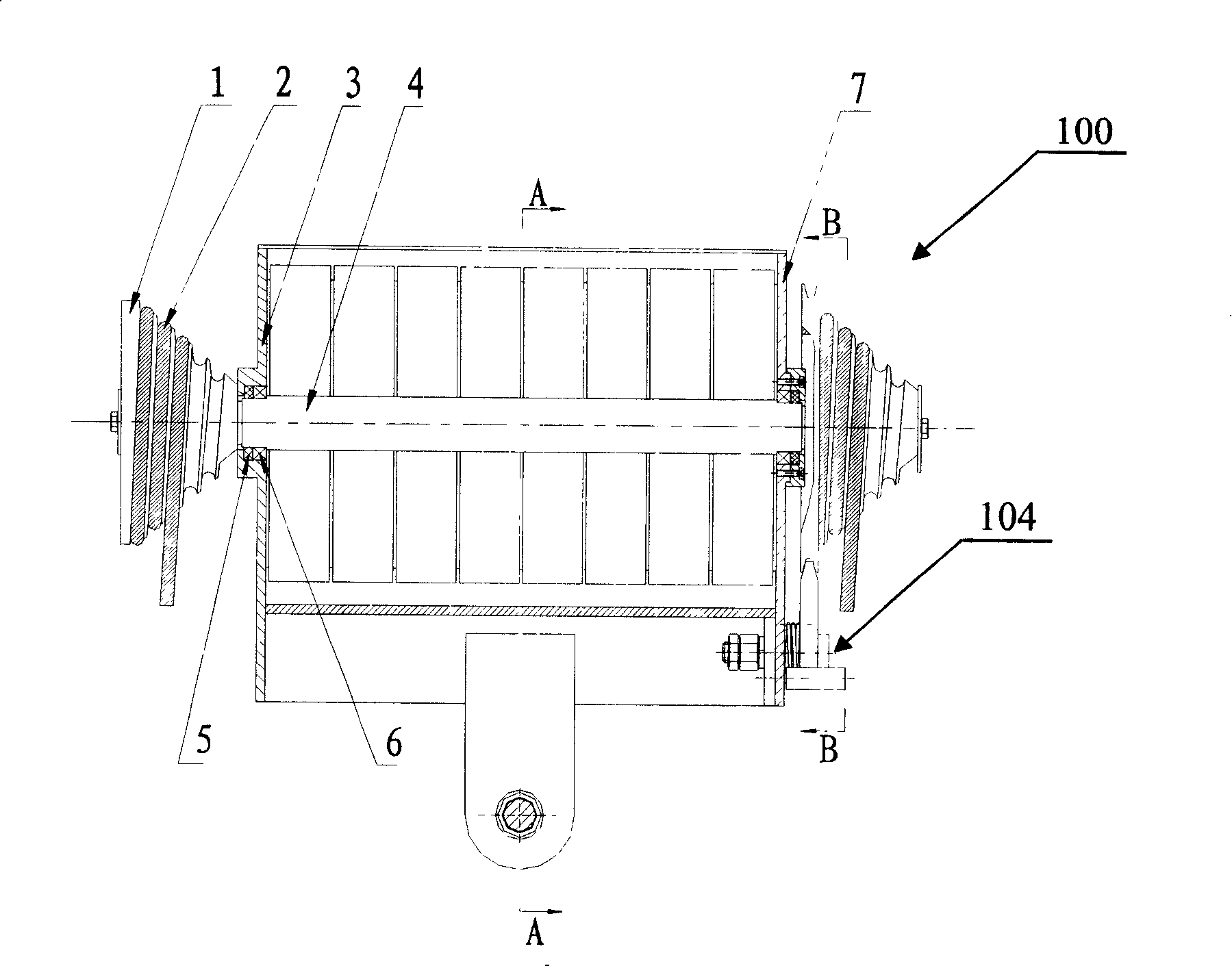
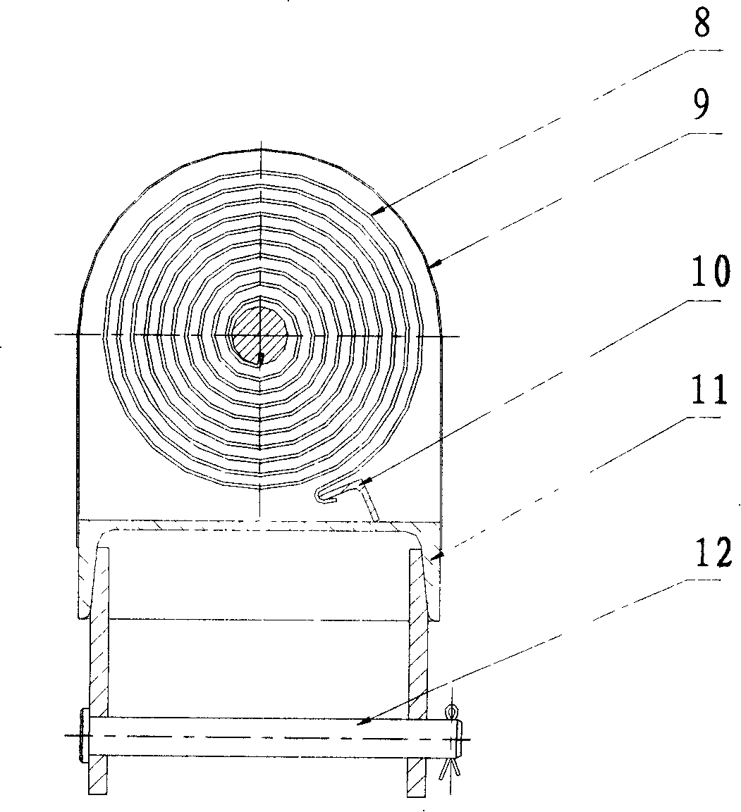
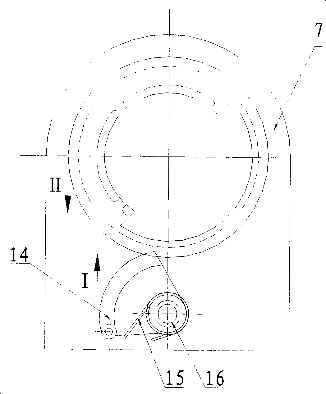
[0063] The structural diagram of the constant tension spring compensation device 100 of the present invention is as follows Figure 1A , Figure 1B As shown, it mainly includes involute sheave 1, compensation rope 2, left end plate 3, main shaft 4, oil seal 5, bearing 6, right end plate 7, contact flat scroll spring 8, outer cover 9, fixed angle steel 10, installation base plate 11. The pin shaft 12, the wire break stop device 104, etc.

[0064] The contact flat scroll spring 8 in the present embodiment is a variable torque flat scroll spring, and the termination radius of the involute sheave 1 can be determined according to the following relationship: termination radius=start radius×(plane scroll spring termination torque / Plane scroll spring starting torque).

[0065] Wherein the left end plate ...


PUM


Abstract

The invention relates to a compensation device of a spring with constant tension, which essentially comprises a grooved pulley, a compensation rope, a left end plate, a main shaft, an oil seal, a bearing, a right end plate, a contact plane volute spring, an external cover, a fixed angle iron, an installation bottom plate, a hinge pin and a broken wire stopping device; wherein, the grooved pulley is fixed on the main shaft; the compensation rope is coiled and has an end fixed on the grooved pulley and the other end connected with an external contact net; the main shaft is supported on the left end plate and the right end plates by the oil seal and the bearing; the left end plate and the right end plate, the external cover, the fixed angle iron and the installation bottom plate form an enclosed box base; the hinge pin is connected to one side on the installation bottom plate far from the box base which is internally provided with the contact plane volute spring with an inner end bent hook connected with the main shaft and an outer end bent hook connected with the fixed angle iron on the box base. The compensation device of the spring with constant tension provided by the invention is compact in structure, small in size and light in weight. The invention can cause an electrified railway network to keep certain tension and reduce the loss catenary rate of the pantagraphs.

Description

technical field [0001] The invention relates to the technical field of electrified railway catenary power supply, and in particular to a constant tension that can maintain a certain tension of the electrified railway catenary (catcher, catenary and soft span) and reduce the off-line rate of its pantograph Spring compensation device. Background technique [0002] In addition to the expansion and contraction caused by temperature changes, the catenary of electrified railways (support cables, contact wires and soft spans) will also elongate the elastic wires due to creep, wire wear, etc., and the pillars will tilt due to long-term effects. Both the height and tension of the contact suspension have an effect. These factors lead to the occurrence of off-line, which deteriorates the current receiving performance of the catenary, and the increase of tension will cause the catenary to be disconnected, resulting in failure of the catenary operation. [0003] The catenary is arrange...

Claims


Application Information

Patent Timeline
Patent Type & Authority Applications(China)
IPC IPC(8): B60M1/26
Inventor 帖荣俊吴利群帖荣康
Owner 帖荣俊
Why Eureka
Try Eureka