Method for suppressing braking noise, central server, vehicle control module, and storage medium

a technology for reducing noise and braking, applied in the direction of braking systems, vehicle sub-unit features, instruments, etc., can solve the problems of not being able to respond in a flexible way to noise, perceived as unpleasant by vehicle occupants or even persons, and unable to occur braking noise, etc., to achieve more cost-effective products and respond flexibly

Active Publication Date: 2021-03-25
CONTINENTAL TEVES AG & CO OHG
View PDF6 Cites 2 Cited by
  • Summary
  • Abstract
  • Description
  • Claims
  • Application Information

AI Technical Summary

Benefits of technology

[0012]By means of the method according to an aspect of the invention at least part of the braking noise suppression can be relocated to a central server, which enables a more flexible response to events or noises occurring. In particular, the central server can be responsible for a multiplicity of vehicles or a plurality of vehicles, for example, of a manufacturer or a fleet of vehicles. The central server allows vehicles to be monitored from a central point even during their operation, and response instructions also to be specified based on data which are only produced during the operation of vehicles.
[0015]The response instructions are intended to be transferred to one or more vehicles where they are used to support the suppression of braking noise. The response instructions may also contain general measures for the improvement of quality, comfort and / or performance of a vehicle condition. This can be, for example, a suppression or modification of a braking noise, for example by changing the braking force distribution between front and rear axle, or else an increase in the brake response performance by detection of the braking state, for example on a wet road surface due to rain. Other measures for improving the quality, comfort or performance of a vehicle may form an integral part of the response instructions. In particular, if these are independent of braking noise this can be interpreted as an independent aspect of the invention.
[0036]The method just described, which is executed in a vehicle, corresponds to the method described above, which is executed in a central server. The vehicle sends the braking state data to the central server and receives the response instructions accordingly, which it can apply to the suppression of braking noise. This results in the advantages described above. In particular, it allows a much more flexible response to different situations or driving styles or even changes due to wear or vehicle modifications.
[0043]This method allows a flexible adaptation of the procedures to driving styles of drivers in the prevention of braking noise or else in terms of general quality, comfort or performance features. Therefore, in particular, the driving profiles already described above can be applied, wherein the corresponding response instructions of the driving profile are used which best suit the driving style.
[0078]The existing data can be used, for example, to create realistic driving profiles of the users. Thus, for example, it is possible to create a usage profile which covers, for example, the driving behavior of 99% of the drivers. A new product to be developed can then be designed for this group of users, for example. This allows unnecessarily high design criteria, which can make a product disproportionately more expensive, to be avoided. The final one percent of users can then be filtered out, for example, using the data analysis and referred for a shorter service interval or upgrading with more robust components.
[0080]A mobile data collection also enables a large number of potential applications. For example, it is possible to carry out a real-time evaluation of vehicle data, for example, in combination with a real-time response in order to adjust vehicle parameters accordingly. It is possible to respond flexibly to different types of new situations by using the deep-learning optimization method and so vehicle parameters can be adjusted. By comparison of different data sets, new and more robust products can be developed. By means of user profiles or driving profiles obtained, more cost-effective products can be produced.

Problems solved by technology

Braking noise can occur in many operating situations and can be perceived as unpleasant by vehicle occupants or even persons outside the vehicle.
A disadvantage of the known designs is that noise events and responses must be defined in advance, which makes it no longer possible to respond in a flexible way to noise events occurring in the actual operation of the vehicle.

Method used


Image

  • Method for suppressing braking noise, central server, vehicle control module, and storage medium
  • Method for suppressing braking noise, central server, vehicle control module, and storage medium

Examples


Embodiment Construction

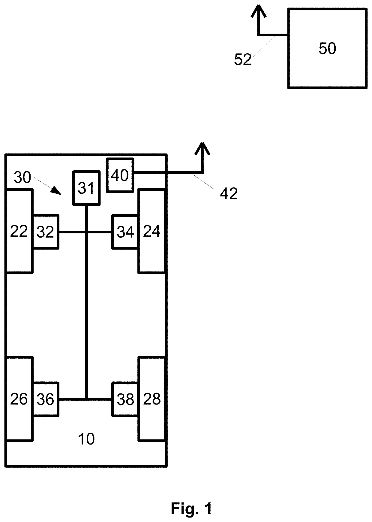
[0089]FIG. 1 shows a schematic diagram of a vehicle in the form of a motor vehicle 10 and a central server 50. These are each designed for carrying out methods according to an aspect of the invention in accordance with relevant exemplary embodiments.

[0090]The motor vehicle 10 has a left-hand front wheel 22, a right-hand front wheel 24, a left-hand rear wheel 26 and a right-hand rear wheel 28. The motor vehicle 10 also comprises a braking system 30. This has a central unit 31, which is designed to generate a braking pressure. This can be, for example, a hydraulic pump and / or a brake cylinder with an attached brake pedal. The braking system 30 further comprises a left front brake unit 32, a right front brake unit 34, a left rear brake unit 36 and a right rear brake unit 38. The brake units 32, 34, 36, 38 are each assigned to one of the wheels 22, 24, 26, 28 to decelerate the respective wheel.

[0091]The motor vehicle 10 also comprises a vehicle control module 40, which is connected to a...


PUM


Abstract

A method for suppressing braking noise in a vehicle by a central server, methods for suppressing braking noise in a vehicle to be carried out in a vehicle, and an associated central server, an associated vehicle control module and an associated data storage medium are disclosed. The data processing is divided between the vehicle and the central server.

Description

CROSS REFERENCE TO RELATED APPLICATIONS[0001]This application is the U.S. National Phase Application of PCT International Application No. PCT / EP2018 / 067272, filed Jun. 27, 2018, which claims priority to German Patent Application No. 10 2017 213 056.3, filed Jul. 28, 2017, the contents of such applications being incorporated by reference herein.FIELD OF THE INVENTION[0002]The invention relates to a method for suppressing braking noise in a number of vehicles by means of a central server, methods for suppressing braking noise in a vehicle, a central server, an associated vehicle control module and a non-volatile computer-readable storage medium.BACKGROUND OF THE INVENTION[0003]Vehicles, in particular motor vehicles or rail-bound vehicles, usually have braking systems which are used for decelerating the vehicle. Braking noise can occur in many operating situations and can be perceived as unpleasant by vehicle occupants or even persons outside the vehicle. Therefore, procedures have alr...

Claims


Application Information

Patent Timeline
Patent Type & Authority Applications(United States)
IPC IPC(8): B60T8/172B60T8/1766B60T8/32B60T17/22G07C5/00
CPCB60T8/172B60T8/1766B60T8/1705B60T17/221G07C5/008B60T8/321B60T8/885B60T17/228B60W40/09B60T2201/124B60T2220/02B60T2270/406B60W2540/30B60T17/22B60T7/18B60T8/00G07C5/08B60Y2306/09B60Y2400/81B60Y2200/10B60Y2200/30B60T8/3235B60T2220/04B60T2270/60
Inventor GÄDKE, MARTINVOGT, MICHAELBACH, UWEBECKHAUS, ARNEHEINZ, SIMONMENTES, MUSTAFALABUDA, MICHAELSTONE, JONATHANGARRO, IGNACIOKALYANASUNDARAM, VIGNESHWAR
Owner CONTINENTAL TEVES AG & CO OHG
Why Eureka
Try Eureka