Leg and abdomen exerciser
An exerciser and leg technology, which is applied in the field of exerciser, can solve the problems of insufficient practicability, single exercise part, and inability to exercise legs, etc., so as to increase the difficulty of abdominal exercise, increase the intensity of abdominal exercise, increase the The effect of leg exercise intensity
- Summary
- Abstract
- Description
- Claims
- Application Information
AI Technical Summary
Problems solved by technology
Method used
Image
Examples
Embodiment 1
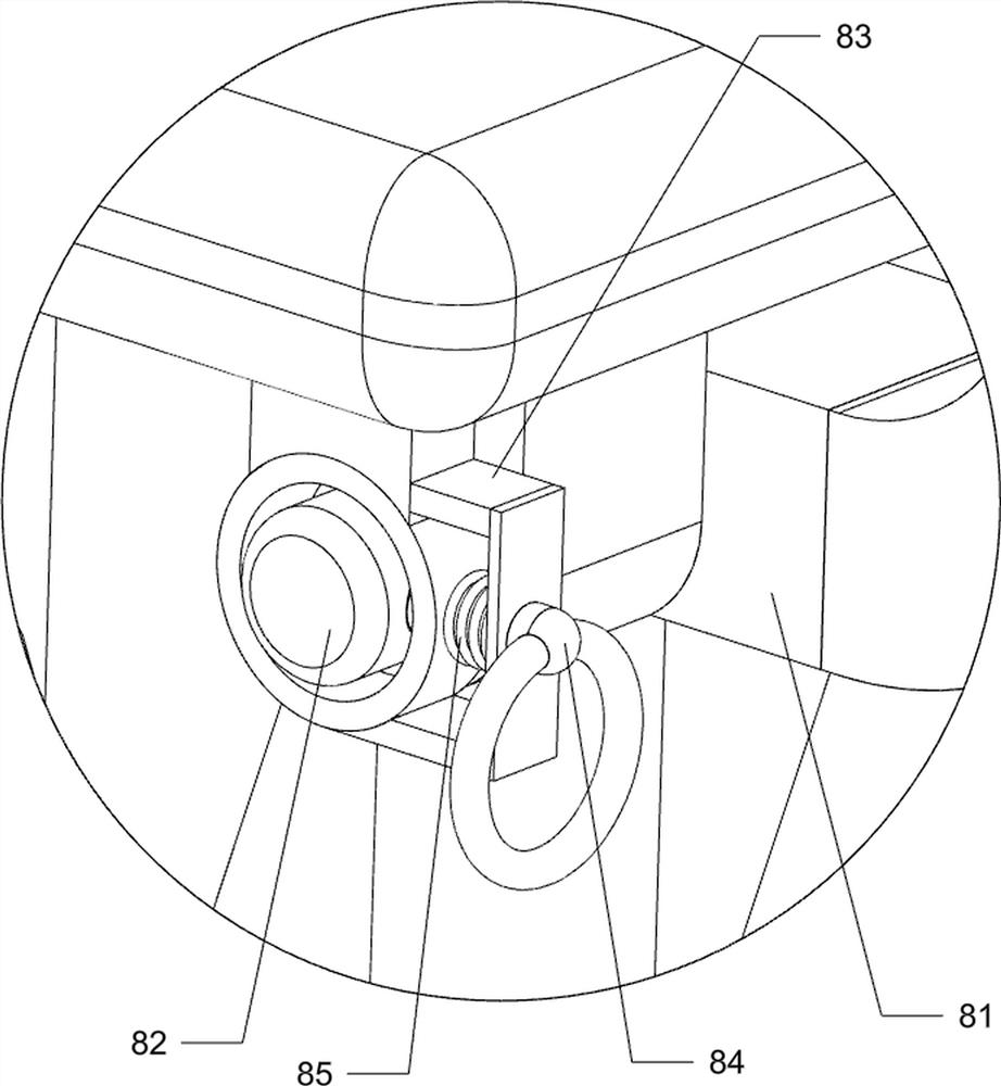
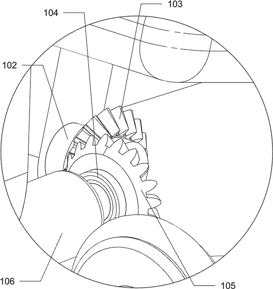
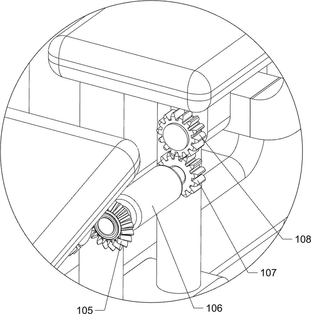
[0032] A leg and abdominal exerciser such as figure 1 , figure 2 , image 3 , Figure 4 , Image 6 with Figure 7 As shown, it includes a base plate 1, a first support frame 2, a second support frame 3, a cushion 4, an abdominal exercise structure 5, a movable handle mechanism 6, a leg exercise structure 7 and a leg limit mechanism 8, and the top of the base plate 1 The first support frame 2 is connected to the left side, the second support frame 3 is connected to the top right side of the bottom plate 1, the cushion 4 is connected to the top right side of the first support frame 2, and the abdomen exercise structure 5 is arranged on the cushion 4, and the abdomen exercise structure 5 A movable handle mechanism 6 is arranged on the top, a leg exercising structure 7 is arranged on the first support frame 2 , and a leg limiting mechanism 8 is arranged on the leg exercising structure 7 .
[0033] Abdominal exercise structure 5 comprises by frame 51, the first connecting sha...
Embodiment 2
[0039] On the basis of Example 1, such as Figure 5 As shown, it also includes a handle trigger mechanism 9, and the handle trigger mechanism 9 includes a mounting frame 91, a supporting plate 92, a support spring 93, a guide frame 94, a push block frame 95 and a third return spring 96, the first support frame 2 The left side of the upper part is connected with a mounting frame 91, and the middle part of the mounting frame 91 is connected with two support springs 93, and a supporting plate 92 is connected between the tops of the two supporting springs 93, and the supporting plate 92 is in contact with the frame 51, and the mounting frame 91 The front and rear sides of the guide frame 94 are connected with a guide frame 94, the guide frame 94 is slidably connected with a push block frame 95, the push block frame 95 cooperates with the frame 51 and the top block 64, and the push block frame 95 is connected with the guide frame 94. The third return spring 96 .
[0040] Support s...
Embodiment 3
[0044] On the basis of Example 2, such as image 3 As shown, a weight-increasing mechanism 11 is also included, and the weight-increasing mechanism 11 includes a connecting rod 111, a first pulley 112, a second pulley 113, a fixed guide support column 114, a rope 115, a sliding plate frame 116 and a weight 117. The lower part of the front side of the side fixed frame 73 is connected with a connecting rod 111, the top right front side of the bottom plate 1 is rotatably connected with a first pulley 112, and the right front side of the bottom plate 1 top is connected with a fixed guide support column 114, and the fixed guide support column 114 is located at the first pulley 112. On the right front side, a second pulley 113 is rotatably connected to the top of the fixed guide support column 114, a sliding frame 116 is slidably connected to the fixed guide support column 114, a rope 115 is connected to the connecting rod 111, and the tail end of the rope 115 is bypassed by the firs...
PUM
 Abstract
Description
Claims
Application Information
 - R&D
- Intellectual Property
- Life Sciences
- Materials
- Tech Scout
- Unparalleled Data Quality
- Higher Quality Content
- 60% Fewer Hallucinations
Browse by: Latest US Patents, China's latest patents, Technical Efficacy Thesaurus, Application Domain, Technology Topic, Popular Technical Reports.
© 2025 PatSnap. All rights reserved.Legal|Privacy policy|Modern Slavery Act Transparency Statement|Sitemap|About US| Contact US: help@patsnap.com


