Topological structure and modulation method of two-way wireless power transmission for electric vehicles

A two-way radio, electric vehicle technology, applied in electric vehicle charging technology, electric vehicles, power management and other directions, can solve the problems of huge harmonic content of the power grid, affecting power quality, and inability to realize batteries, reducing current harmonic content, The effect of reducing switching losses and improving grid quality

Active Publication Date: 2022-07-01
HARBIN INST OF TECH
View PDF5 Cites 0 Cited by
  • Summary
  • Abstract
  • Description
  • Claims
  • Application Information

AI Technical Summary

Problems solved by technology

[0003] The present invention aims to solve the problem that the existing wireless charging structure for high-power electric vehicles introduces huge harmonic content to the power grid, affects the quality of power energy, and cannot realize the power feeding of the battery to the power grid.

Method used


Image

  • Topological structure and modulation method of two-way wireless power transmission for electric vehicles
  • Topological structure and modulation method of two-way wireless power transmission for electric vehicles
  • Topological structure and modulation method of two-way wireless power transmission for electric vehicles

Examples


specific Embodiment approach 1

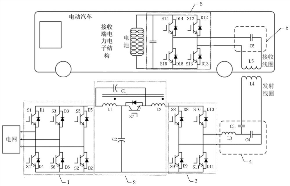
[0045] Specific implementation mode 1: refer to figure 1 Specifically describe this embodiment, the electric vehicle two-way wireless power transmission topology structure described in this embodiment, the topology structure includes a transmitter converter and a receiver converter,

[0046] The transmitter converter includes a unit power correction module 1, a quasi-Z source converter 2, a high-frequency inverter module 3, a transmitter LCC type compensation network 4 and a transmitter coil,

[0047] The receiver converter includes a receiver coil, a receiver compensation network 5 and a bidirectional controllable rectifier bridge 6,

[0048] The unit power correction module 1 is used to perform power factor correction on the AC power output from the grid, and the corrected DC power is transmitted to the quasi-Z source converter 2, and is also used to perform power factor correction on the boosted DC power to obtain the corrected DC power. AC transmission to the grid;

[00...

specific Embodiment approach 2

[0055] Embodiment 2: This embodiment further describes the two-way wireless power transmission topology of electric vehicles described in Embodiment 1. In this embodiment, the unit power correction module 1 is composed of 6 switch tubes and 6 diodes The three-phase full-bridge inverter circuit.

[0056] In this embodiment, the circuit structure of the unit power correction module 1 is as follows figure 1 shown.

specific Embodiment approach 3

[0057] Embodiment 3: This embodiment further describes the two-way wireless power transmission topology for electric vehicles described in Embodiment 2. In this embodiment, the quasi-Z source converter 2 includes capacitors C1-C2, coupled inductors L1- L2 and switch tube S7,

[0058] The positive output end of the unit power correction module 1 is connected to the positive electrode of the capacitor C1 and one end of the coupling inductor L1 at the same time. One end of the inductor L2 and the negative electrode of the capacitor C1, the other end of the inductor L2 is connected to the positive input end of the high frequency inverter module 3,

[0059] The other end of the capacitor C2 is connected to the negative output end of the unit power correction module 1 and the negative input end of the high frequency inverter module 3 at the same time.

[0060] In this embodiment, the circuit structure of the quasi-Z source converter 2 is as follows figure 1 shown.


PUM


Abstract

The invention discloses a topology structure and a modulation method for two-way wireless power transmission of electric vehicles, and relates to the field of power transmission. The invention aims to solve the problems of introducing huge harmonic content into the power grid, affecting the power quality, and failing to realize the power feeding of the battery to the power grid in the existing wireless charging structure for high-power electric vehicles. The three-phase full-bridge inverter circuit is used to correct the power factor of the grid-side output to ensure that the current and voltage phases of the grid-side are the same. Then, the quasi-Z source converter based on coupled inductance is used to buck and adjust the bus voltage. After adjustment, the high-frequency inverter is carried out through the H-bridge of the high-frequency inverter module to obtain high-frequency alternating current. The high-frequency alternating current is transmitted to the receiving coil and the resonant network of the receiving end compensation network through the resonant network and the transmitting coil. Finally, the energy is transferred to the battery through the bidirectional controllable rectifier bridge. It is used to charge the battery.

Description

technical field [0001] The invention relates to a bidirectional transmission structure of electric energy and a modulation method. It belongs to the field of power transmission. Background technique [0002] At present, most of the functions of the transmitter converter of electric vehicle wireless power charging technology are: single-phase / three-phase power grid outputs DC voltage through uncontrolled rectification. transmitted to the resonant network. The problems brought about by such a structure are: 1) For wireless charging of high-power electric vehicles without PFC correction, a huge harmonic content will be introduced into the power grid, which will affect the power quality; 2) The application of uncontrolled rectification of the transmitter at the transmitter will limit the electric power The direction of the wireless power flow of the car cannot realize the feeding of the battery to the grid. SUMMARY OF THE INVENTION [0003] The invention aims to solve the p...

Claims


Application Information

Patent Timeline
Patent Type & Authority Patents(China)
IPC IPC(8): B60L53/12B60L55/00
CPCB60L53/12B60L55/00Y02T90/16
Inventor 那拓扑张明涛徐国强唐佳棋李为汉张千帆
Owner HARBIN INST OF TECH
Why Eureka
Try Eureka