Electric vehicle bidirectional wireless power transmission topological structure and modulation method
A two-way radio and topology technology, applied in electric vehicle charging technology, electric vehicle, vehicle energy storage, etc., can solve the problems of inability to realize batteries, affecting power quality, and huge harmonic content of the power grid, so as to improve the quality of the power grid and improve the Working efficiency, the effect of eliminating the output inductor current ripple
- Summary
- Abstract
- Description
- Claims
- Application Information
AI Technical Summary
Problems solved by technology
Method used
Image
Examples
specific Embodiment approach 1
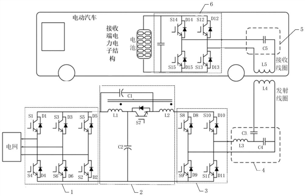
[0045] Specific implementation mode one: refer to figure 1 Describe this embodiment in detail, the topology structure of two-way wireless power transmission for electric vehicles described in this embodiment, the topology structure includes a transmitter converter and a receiver converter,
[0046] The transmitter converter includes a unit power correction module 1, a quasi-Z source converter 2, a high-frequency inverter module 3, a transmitter LCC type compensation network 4 and a transmitter coil,
[0047] The receiver converter includes a receiver coil, a receiver compensation network 5 and a bidirectional controllable rectifier bridge 6,
[0048] The unit power correction module 1 is used to correct the power factor of the alternating current output from the grid, and transmit the corrected direct current to the quasi-Z source converter 2, and is also used to perform power factor correction on the boosted direct current to obtain the corrected AC transmission to the grid;...
specific Embodiment approach 2
[0055] Specific embodiment 2: This embodiment is to further explain the topological structure of electric vehicle two-way wireless power transmission described in specific embodiment 1. In this embodiment, the unit power correction module 1 is composed of 6 switching tubes and 6 diodes three-phase full-bridge inverter circuit.
[0056] In this embodiment, the circuit structure of the unit power correction module 1 is as follows figure 1 shown.
specific Embodiment approach 3
[0057] Specific embodiment three: This embodiment is a further description of the two-way wireless power transmission topology of electric vehicles described in specific embodiment two. In this embodiment, the quasi-Z source converter 2 includes capacitors C1-C2, coupling inductors L1- L2 and switch tube S7,
[0058] The positive output terminal of the unit power correction module 1 is simultaneously connected to the positive terminal of the capacitor C1 and one end of the coupling inductor L1, and the other end of the coupling inductor L1 is simultaneously connected to one end of the capacitor C2 and one end of the switch tube S7, and the other end of the switch tube S7 is simultaneously connected to the coupling One end of the inductor L2 is connected to the negative pole of the capacitor C1, and the other end of the inductor L2 is connected to the positive input terminal of the high frequency inverter module 3,
[0059] The other end of the capacitor C2 is simultaneously co...
PUM
 Abstract
Description
Claims
Application Information
 - R&D
- Intellectual Property
- Life Sciences
- Materials
- Tech Scout
- Unparalleled Data Quality
- Higher Quality Content
- 60% Fewer Hallucinations
Browse by: Latest US Patents, China's latest patents, Technical Efficacy Thesaurus, Application Domain, Technology Topic, Popular Technical Reports.
© 2025 PatSnap. All rights reserved.Legal|Privacy policy|Modern Slavery Act Transparency Statement|Sitemap|About US| Contact US: help@patsnap.com


