
An electrocatalytic oxidation wastewater treatment device

An electrocatalytic oxidation and wastewater treatment technology, which is applied in water/sewage treatment, water/sewage multi-stage treatment, water/sludge/sewage treatment, etc. It can solve the problem of poor aeration effect, restrict wastewater treatment, increase electrocatalysis Problems such as the processing load of the oxidation device

Active Publication Date: 2021-05-18
SHANDONG LONGANTAI ENVIRONMENTAL PROTECTION SCI TECH CO LTD
View PDF8 Cites 0 Cited by
  • Summary
  • Abstract
  • Description
  • Claims
  • Application Information

AI Technical Summary

Problems solved by technology

[0002] When electrocatalytic oxidation is used for wastewater treatment, due to the high energy consumption of the electrocatalytic oxidation device and the rapid corrosion of the plate, the wastewater is pretreated by aeration and then the pretreated wastewater is electrocatalytically oxidized The method can reduce energy consumption, prolong the service life of the plate, and improve the treatment efficiency of electrocatalytic oxidation. However, in the existing domestic aeration equipment, the depth of aeration is often relatively shallow. In the case of a deep aeration tank The aeration effect on the bottom wastewater is poor, which restricts the effect of wastewater treatment and increases the processing load of the electrocatalytic oxidation device, and the aeration can effectively remove the waste gas dissolved in the wastewater, but the aeration process The froth generated in the air will restrain the waste gas, so that the waste gas will dissolve in the waste water again in the froth, which will delay the aeration time and reduce the work efficiency. Therefore, we have designed an electrocatalytic oxidation wastewater treatment device

Method used


Image

  • An electrocatalytic oxidation wastewater treatment device
  • An electrocatalytic oxidation wastewater treatment device
  • An electrocatalytic oxidation wastewater treatment device

Examples


Embodiment Construction

[0015] In order to make the purpose, technical solutions and advantages of the embodiments of the present invention clearer, the technical solutions in the embodiments of the present invention will be clearly and completely described below in conjunction with the drawings in the embodiments of the present invention. Obviously, the described embodiments It is a part of embodiments of the present invention, but not all embodiments. Based on the embodiments of the present invention, all other embodiments obtained by persons of ordinary skill in the art without creative efforts fall within the protection scope of the present invention.

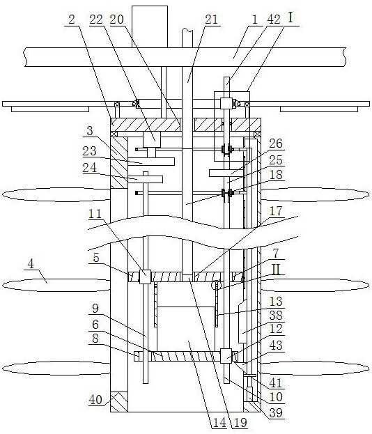
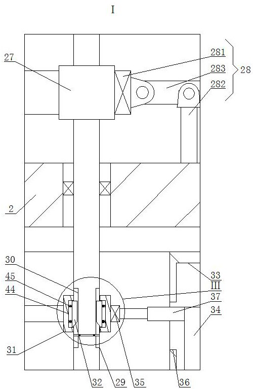
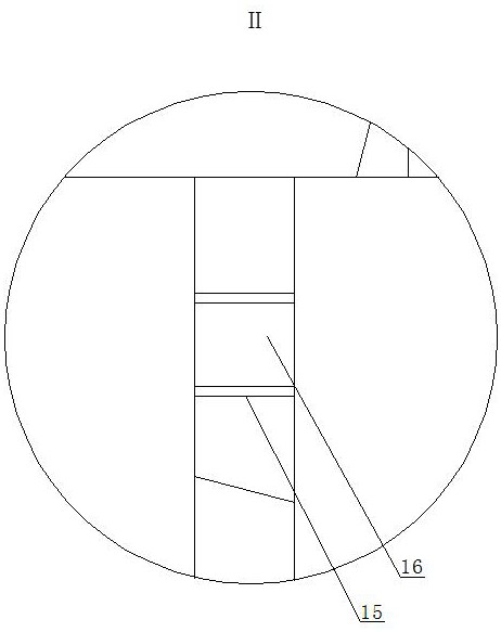
[0016]An electrocatalytic oxidation wastewater treatment device, as shown in the figure, includes a bracket 1, a top plate 2, a vertical pipe 3, and a stirring blade 4. The top plate 2 is fixedly installed on the support 1, and the vertical pipe is installed on the bottom surface of the top plate 2 through a sealed bearing. 3. A number of stirring...


PUM


Abstract

An electrocatalytic oxidation wastewater treatment device, comprising a bracket, a top plate, a standpipe, and stirring blades, the top plate is fixedly installed on the support, the bottom surface of the top plate is installed with a vertical pipe through a sealed bearing, and several stirring blades are fixedly installed on the outer periphery of the vertical pipe, The vertical pipe is provided with a first circular plate, a second circular plate is provided below the first circular plate, first through holes are respectively provided on both sides of the top surface of the first circular plate, and the top surface of the second circular plate is provided with the first through hole. The second through hole corresponding to the hole, one of the first through holes is provided with a first reciprocating screw, and the other second through hole is provided with a second reciprocating screw, the first reciprocating screw and the second reciprocating screw are respectively through the corresponding second through hole. The invention has an ingenious structure, can improve the effect of aeration, prolong the depth of aeration, and can inject air into waste water of different depths, improve the effect of aeration, and can periodically spray water floating on the water surface during use. The froth is broken to reduce the redissolution of waste gas into the wastewater and improve the aeration efficiency.

Description

technical field [0001] The invention belongs to the field of wastewater treatment devices, in particular to an electrocatalytic oxidation wastewater treatment device. Background technique [0002] When electrocatalytic oxidation is used for wastewater treatment, due to the high energy consumption of the electrocatalytic oxidation device and the rapid corrosion of the plate, the wastewater is pretreated by aeration and then the pretreated wastewater is electrocatalytically oxidized The method can reduce energy consumption, prolong the service life of the plate, and improve the treatment efficiency of electrocatalytic oxidation. However, in the existing domestic aeration equipment, the depth of aeration is often relatively shallow. In the case of a deep aeration tank The aeration effect on the bottom wastewater is poor, which restricts the effect of wastewater treatment and increases the processing load of the electrocatalytic oxidation device, and the aeration can effectively...

Claims


Application Information

Patent Timeline
Patent Type & Authority Patents(China)
IPC IPC(8): C02F7/00C02F9/08
CPCC02F1/4672C02F7/00C02F2303/12Y02W10/10
Inventor 代春龙张华东魏明勇孙垂刚
Owner SHANDONG LONGANTAI ENVIRONMENTAL PROTECTION SCI TECH CO LTD
Learn More