Self-locking wire pressing device for weak current engineering cable wiring

A technology of weak current engineering and crimping device, which is applied in the direction of electrical components, etc., can solve the problems of easy entanglement of cables and achieve the effects of improving efficiency and accuracy, preventing bending and entanglement, and good wiring effect

Active Publication Date: 2021-02-19
铜陵百安科技股份有限公司
View PDF5 Cites 3 Cited by
  • Summary
  • Abstract
  • Description
  • Claims
  • Application Information

AI Technical Summary

Problems solved by technology

[0004] The purpose of the present invention is to solve the problem that the cables in the wiring cabinet are e...

Method used


Image

  • Self-locking wire pressing device for weak current engineering cable wiring
  • Self-locking wire pressing device for weak current engineering cable wiring
  • Self-locking wire pressing device for weak current engineering cable wiring

Examples


Embodiment 1

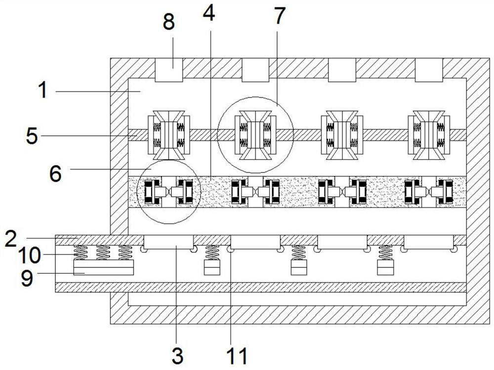
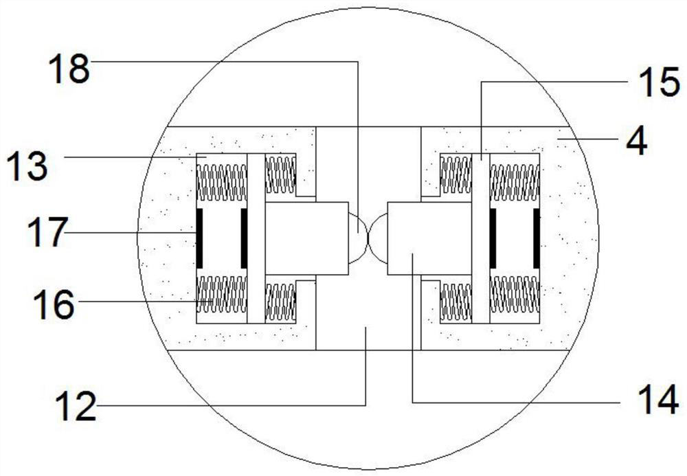
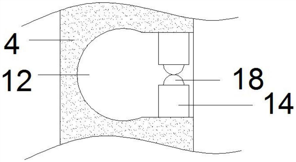
[0028] refer to Figure 1-6 , a self-locking crimping device for cable wiring in weak current projects, comprising a device box 1, a wire inlet pipe 2 arranged at the lower end of the device box 1 and a plurality of wire outlets 8 arranged at the top of the device box 1, the wire inlet pipe A plurality of cable management openings 3 are opened above 2, and the two ends of the connection plate 4 are connected with the inner side wall of the device box 1 and arranged directly above the line inlet pipe 2, and a plurality of first locking mechanisms 6 are arranged on the connection plate 4, The first thread locking mechanism 6 includes a wire slot 12 provided on the connecting plate 4. The inner side of the wire slot 12 is arc-shaped, and the outer side is a square opening shape. The opening of the wire slot 12 is symmetrically opened with T-shaped Slot 13, one end of extrusion block 14 is inserted into the T-shaped slot 13 and connected with the limiting plate 15, and the limitin...

Embodiment 2

[0030] Such as Figure 1-6 As shown, this embodiment is basically the same as Embodiment 1. In order to improve the smoothness of the placement of the main cable inside the wire inlet pipe 2, preferably, a plurality of wire crimping plates 9 are arranged inside the wire inlet pipe 2 to crimp the wires. The plate 9 is connected with the upper end of the inlet pipe 2 through the first elastic member 10 .

[0031] In order to further improve the stability of the fixing of the total cable, preferably, the wire pressing plate 9 is in an inverted arc shape.

Embodiment 3

[0033] Such as Figure 1-6 As shown, this embodiment is basically the same as Embodiment 1. In order to prevent the cables from being scratched by the side of the cable management port 3 when they are pulled out from the side of the cable management port 3, preferably, the two sides of the cable management port 3 are arranged symmetrically. There are rollers 11, and the rollers 11 are rotatably connected with the cable management port 3.

[0034] In order to facilitate the entry of cables into the wire slot 12 and prevent damage to the cables, preferably, balls 18 are provided at the adjacent ends of the two symmetrical extrusion blocks 14 , and the balls 18 are rotatably connected to the extrusion blocks 14 .

[0035] In order to improve the extrusion stability of the extruding block 14 , preferably, two magnet blocks 17 of the same polarity are arranged symmetrically adjacent to the limiting plate 15 and the T-shaped slot 13 .


PUM


Abstract

The invention discloses a self-locking wire pressing device for weak current engineering cable wiring, and relates to the technical field of cable wiring. The device comprises a device box, a wire inlet pipe and a wire outlet, a plurality of wire arranging openings are formed at the upper portion of the wire inlet pipe, and a connecting plate is arranged right above the wire inlet pipe; a plurality of first wire locking mechanisms are arranged on the connecting plate, each first wire locking mechanism comprises a wire through groove, and T-shaped grooves are symmetrically formed at the two sides of each wire through groove. One end of an extrusion block is inserted in each T-shaped groove to be connected with a limiting plate, and the two sides of the limiting plate are connected with thetwo sides of the T-shaped groove through second elastic pieces correspondingly. A set of parallel connecting rods are arranged at the upper end of a connecting plate, a plurality of second wire locking mechanisms are arranged between the connecting rods, and each second wire locking mechanism comprises a protection frame arranged between the two connecting rods and arc-shaped plates symmetricallyarranged at the two sides in the protection frame. The self-locking wire pressing device overcomes the defects in the prior art, is reasonable in design and is convenient to use, cables in the wiringcabinet can be effectively, clearly and conveniently arranged, and the usage convenience is improved.

Description

technical field [0001] The invention relates to the technical field of cable wiring, in particular to a self-locking crimping device for cable wiring in weak current projects. Background technique [0002] Weak current engineering is a classification of power applications. According to the strength of power transmission power, electric power applications can be divided into two categories: strong power and weak power. The electricity consumption of buildings and buildings generally refers to the weak electricity of AC 220V50Hz and below. It mainly provides electric energy to people and converts electric energy into other energy sources, such as air-conditioning electricity, lighting electricity, power electricity and so on. [0003] Nowadays, most of the daily electrification equipment that people are in contact with daily are weak current projects. Due to the development of science and technology, there are more and more types of electrical appliances used in people's dai...

Claims


Application Information

Patent Timeline
IPC IPC(8): H02G3/08H02G3/18
CPCH02G3/083H02G3/18
Inventor 王效谦罗松志
Owner 铜陵百安科技股份有限公司
Why Eureka
Try Eureka