Adjustable anti-galloping spacer

A spacer and anti-galling technology, which is applied in the direction of mechanical vibration attenuation devices, devices for maintaining the distance between parallel conductors, electrical components, etc., can solve problems affecting workers' construction, adjustment of relative positions of spacers, and extension of construction period, etc., to achieve the suppression of the same period Dancing and non-synchronous dancing, stronger connection structure, firm and stable connection structure

Active Publication Date: 2021-02-19
YANTAI POWER SUPPLY COMPANY OF STATE GRID SHANDONG ELECTRIC POWER
View PDF8 Cites 5 Cited by
  • Summary
  • Abstract
  • Description
  • Claims
  • Application Information

AI Technical Summary

Problems solved by technology

[0004] The object of the present invention is to provide an adjustable anti-galling spacer to solve the problem that most of the spacers cannot adjust the relative position of the existing spacer proposed in the background technology, which affects the The construction of workers, which leads to the problem that the construction period is extended

Method used


Image

  • Adjustable anti-galloping spacer
  • Adjustable anti-galloping spacer
  • Adjustable anti-galloping spacer

Examples


Embodiment 1

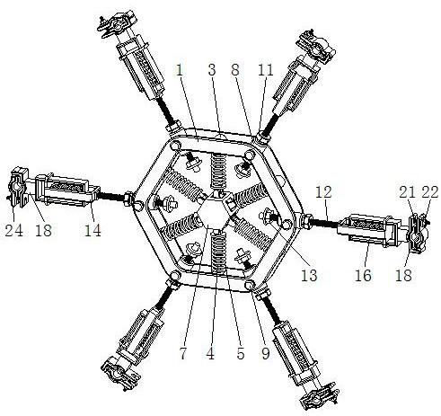
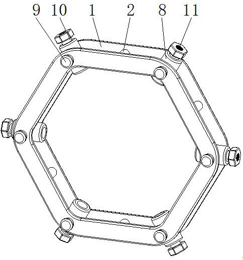
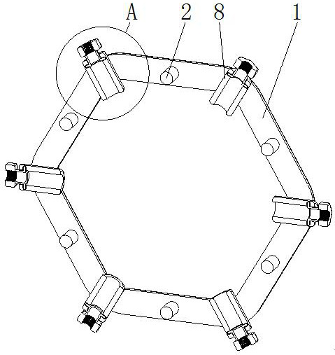
[0026] see Figure 1-6 , the present invention provides a technical solution: an adjustable anti-galling spacer, including a spacer body 1, a fixed rod 2 is fixedly installed inside the spacer body 1, and a sleeve ring block is movably socketed on the outside of the fixed rod 2 3. The bottom of the sleeve ring block 3 is fixedly installed with a telescopic sleeve rod 4, and the outer movable sleeve of the telescopic sleeve rod 4 is connected with an anti-galling spring 5, and the bottom of the telescopic sleeve rod 4 is movably installed with a movable base 6, and the bottom of the movable base 6 A fixed center block 7 is fixedly installed, and a socket pipe 8 is installed movable inside the spacer body 1, and the inner movable socket of the socket pipe 8 is connected with a limit inner ring 10, and the end of the limit inner ring 10 away from the socket pipe 8 is fixedly installed with an adjustment Nut 11, the internal movable socket of adjusting nut 11 is provided with thre...

Embodiment 2

[0029]On the basis of Embodiment 1 of the present invention, there are two spacer rod bodies 1, six fixed rods 2, six fixed rods 2 are fixedly installed between the two spacer rod bodies 1 in the form of a circle, and six movable bases 6 , the six movable bases 6 are fixedly installed on the outside of the fixed center block 7 in the form of a circle, and there are six socket ring blocks 3, and the six socket ring blocks 3 are respectively movably socketed on the outside of the six fixed rods 2, and the socket pipe 8 Extension rods 9 are fixedly installed at both ends of the two extension rods 9. One end of the two extension rods 9 away from the socket pipe 8 respectively penetrates the two spacer rod bodies 1 and extends to the outside. There are six socket pipes 8, and the six socket pipes 8 are in a circular motion. Installed between the two spacer rod bodies 1, the inside of the sleeve pipe 8 is provided with a rotating groove that matches the specification and size of the ...


PUM


Abstract

The invention discloses an adjustable anti-galloping spacer which comprises a spacer body. A fixing rod is fixedly installed in the spacer body, a sleeving ring block is movably connected to the exterior of the fixing rod in a sleeving mode, a telescopic sleeve rod is fixedly installed at the bottom of the sleeving ring block, and an anti-galloping spring is movably connected to the exterior of the telescopic sleeve rod in a sleeving mode. A movable base is movably installed at the bottom of the telescopic sleeve rod, a fixed center block is fixedly installed at the bottom of the movable base,a sleeve pipe is movably installed in the spacer body, and a limiting inner ring is movably sleeved with the sleeve pipe. The extending length of the threaded connecting rod can be adjusted through the adjusting nut which is installed in a rotating mode, so that a worker can install electric wires in a long distance and an electric wire in a short distance conveniently, and the inter-phase distance between sub-wires is adjusted. The two ends of the socketed pipe penetrate through the extension rods of the spacer body, so that errors of conductor sag installation can be conveniently adapted and compensated, and workers can conveniently adjust the conductor sag.

Description

technical field [0001] The invention belongs to the technical field of overhead power transmission lines, and in particular relates to an adjustable anti-galling spacer. Background technique [0002] The main purpose of spacer rods for split wires of power transmission lines is to limit the relative movement between the sub-wires and maintain the geometry of the split wires under normal operating conditions. According to the working characteristics of the spacer rods, they can be roughly divided into two categories, namely damping type spacing rods and non-damping spacer rods. [0003] Most of the existing spacers will have blind spots in the adjustment. When the interphase spacing of the wires needs to be fine-tuned, most of the spacers cannot adjust the relative position; for example, the Chinese invention patent with the notification number CN201243187Y discloses An adjustable spacer bar between phases of wires. An adjustment plate and a connection plate are set between ...

Claims


Application Information

Patent Timeline
Patent Type & Authority Applications(China)
IPC IPC(8): H02G7/12H02G7/14
CPCH02G7/125H02G7/14
Inventor 曲恒志贾玉清郭胜田郝英勤周伟王秀娟李培作王华东梁雯孙冰宋方超郭田兴孙兆键李豪史立辉张铭刚于成涛刘文东李之远郝鹤徐晓光凌跃乾董波宋英涛林波徐强李林张焕博赵林梁勇于涛孙建涛张所坤
Owner YANTAI POWER SUPPLY COMPANY OF STATE GRID SHANDONG ELECTRIC POWER
Why Eureka
Try Eureka