
Plastic-coated rotor, motor and fan

A technology of overmolding and rotors, applied in the fields of motors, ventilators, and overmolded rotors, can solve the problems of high technological requirements, difficult shaft sleeve processing, poor reliability, etc. quality effect

Active Publication Date: 2021-11-19
合肥凯邦电机有限公司 +2
View PDF0 Cites 0 Cited by
  • Summary
  • Abstract
  • Description
  • Claims
  • Application Information

AI Technical Summary

Problems solved by technology

The rotor and the shaft of the external rotor motor for small fans are usually assembled by keyway fit or cold press interference fit to ensure its structural strength, and the method of using keyway fit often requires additional bushings and bushing processing. Difficult, high requirements on manufacturability; and interference fit is often less reliable

Method used


Image

  • Plastic-coated rotor, motor and fan
  • Plastic-coated rotor, motor and fan
  • Plastic-coated rotor, motor and fan

Examples


Embodiment 1

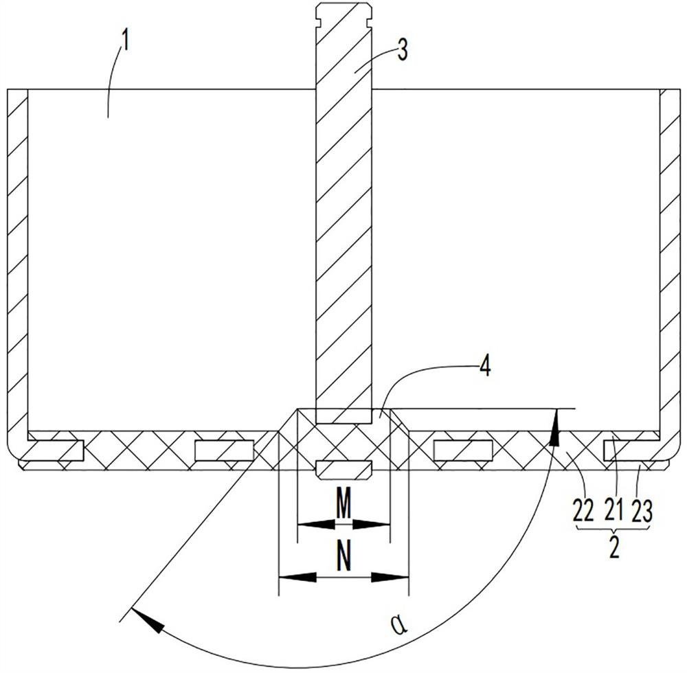
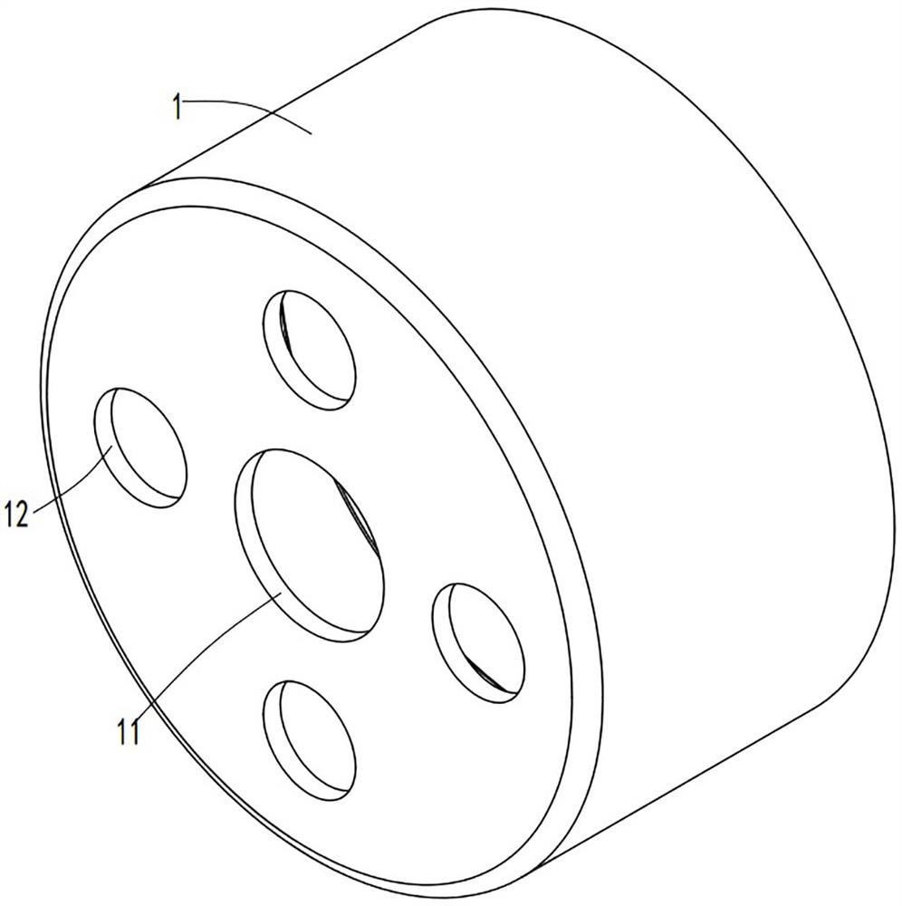
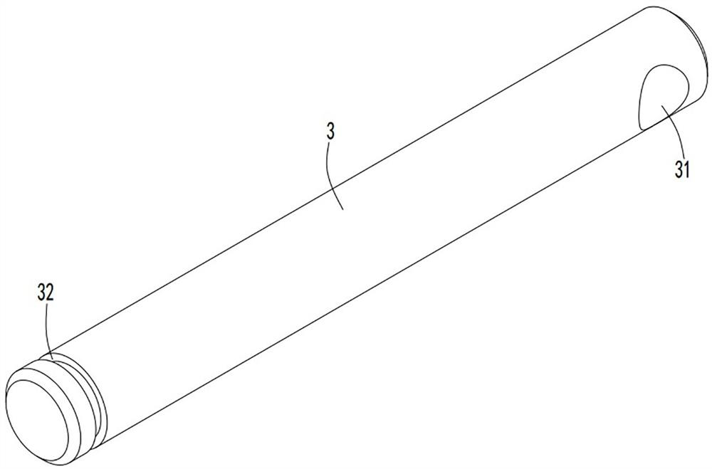
[0025] refer to Figure 1 to Figure 4 , a plastic-coated rotor provided by the present invention includes a rotor housing 1, a plastic-coated body 2 arranged at the bottom of the rotor housing 1, a rotor shaft 3 connected to the plastic-coated body 2, and a plastic-coated body 2 is fitted with the rotor housing 1, and the rotor housing 1, the overmolded body 2, and the rotor shaft 3 are integrally formed, specifically by injection molding.

[0026] The bottom of the rotor housing 1 is provided with a first injection runner 11 at a position corresponding to the rotor shaft 3, and a plurality of second injection runners 12 are uniformly arranged at the bottom of the rotor housing 1; the first injection runner 11 and the second injection molding runner 12 run through the bottom of the rotor housing 1, and the overmolding body 2 is connected with the rotor housing 1 through the first injection molding runner 11 and the second injection molding runner 12. During injection molding ...

Embodiment 2

[0037] In this embodiment, there is no restriction on the distribution of the second injection molding runners 12, as long as the distribution is uniform and the structural strength meets the standard, for example, there are more than four, or there is no need to arrange them in a circular array. The rest of the structures are the same as those in Embodiment 1, and will not be repeated here.

[0038] The present invention is provided with a first injection molding flow channel and a second injection molding flow channel at the bottom of the rotor shell, and the distribution of the injection molding flow channels is even and reasonable, which realizes uniform filling in the injection molding process and facilitates the overmolding body and the rotor shell in the injection molding process. The reliable combination of body improves the reliability of the overmolding process. At the same time, the rotor shaft is provided with a third injection molding flow channel, so that the rot...


PUM


Abstract

The invention relates to the technical field of motors, in particular to a plastic-coated rotor, a motor and a fan. The plastic-coated rotor includes a rotor shell, a plastic-coated body arranged at the bottom of the rotor The body covers the bottom of the rotor housing, and the rotor housing, the overmolded body, and the rotor shaft are integrally formed. The bottom of the rotor housing is provided with a first injection molding channel at the position corresponding to the rotor shaft. Two injection molding runners, the end of the rotor shaft connected to the overmolding body is provided with a third injection molding runner along the radial direction. The distribution of the first injection molding flow channel and the second injection molding flow channel of the present invention is even and reasonable, which realizes uniform filling in the injection molding process, facilitates the reliable combination of the overmolding body and the rotor housing during the injection molding process, and improves the reliability of the overmolding process. sex. At the same time, the rotor shaft is provided with a third injection molding flow channel, so that the rotor shell, the overmolded body and the rotor shaft can be integrally injection molded, which simplifies the process and improves the assembly accuracy.

Description

technical field [0001] The invention relates to the technical field of motors, in particular to a plastic-coated rotor, a motor and a fan. Background technique [0002] Motor, commonly known as "motor", refers to an electromagnetic device that realizes the conversion or transmission of electric energy according to the law of electromagnetic induction. Its main function is to generate driving torque as a power source for electrical appliances or various machinery. Generally speaking, according to the type of working power supply, motors can be divided into DC motors and AC motors. Motors are widely used in machinery manufacturing, household appliances, transportation and other fields, and have become an indispensable part of social life. The ventilator is a machine that relies on the input mechanical energy to increase the gas pressure and discharge the gas. It is a driven fluid machine. Ventilators are widely used in ventilation, dust removal and cooling of factories, mine...

Claims


Application Information

Patent Timeline
Patent Type & Authority Patents(China)
IPC IPC(8): H02K1/28
CPCH02K1/28
Inventor 王浩森高晓峰李庆杨欢侯海杰钟绍民
Owner 合肥凯邦电机有限公司
Learn More