
U-shaped pipe flaring device

A U-shaped pipe and fixture technology, applied in the field of U-shaped pipes, can solve the problems of high production cost, U-shaped pipe rupture, fixture wear, etc., and achieve the effects of improving the yield rate, prolonging the service life and reducing the production cost.

Inactive Publication Date: 2021-02-23
郭小求
View PDF13 Cites 1 Cited by
  • Summary
  • Abstract
  • Description
  • Claims
  • Application Information

AI Technical Summary

Problems solved by technology

The U-shaped pipe fixture in the existing U-shaped pipe reaming device is a rigid structure as a whole. During the expansion process, there will be uneven stress, which will easily cause the U-shaped pipe to break, and the fixture will be severely worn, requiring frequent Maintenance and replacement, high production cost

Method used


Image

  • U-shaped pipe flaring device
  • U-shaped pipe flaring device
  • U-shaped pipe flaring device

Examples


Embodiment Construction

[0034] The present invention will be further explained below in conjunction with the accompanying drawings and specific embodiments. It should be understood that the following specific embodiments are only used to illustrate the present invention and are not intended to limit the scope of the present invention.

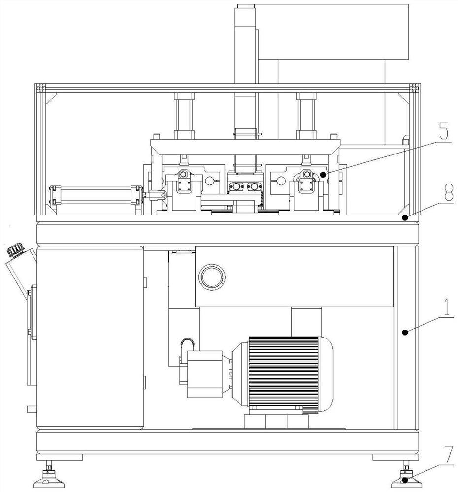
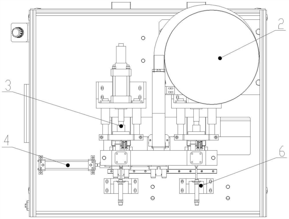
[0035] see figure 1 , 2 As shown, the present invention discloses a U-shaped tube flaring device, including a frame 1, a U-shaped tube feeding mechanism 2, a flaring mechanism 3, a pushing mechanism 4, a clamp assembly 5, a feeding mechanism 6 and a PLC controller , the bottom of the frame 1 is fixed with a disc leg 7, the top of the frame 1 is provided with a workbench 8, and the middle part of the workbench 8 is provided with a push mechanism 4, and two groups of Clamp assembly 5, one side of the two groups of clamp assemblies 5 is provided with a blanking mechanism 6, the other side is provided with a flaring mechanism 3, and the workbench 8 is also provided with a ...


PUM


Abstract

The invention relates to a U-shaped pipe flaring device. The device mainly solves the problem that a U-shaped pipe clamp in an existing U-shaped pipe flaring device is of a rigid structure as a whole,and stress is uneven in the flaring machining process. The U-shaped pipe flaring device comprises a rack, a U-shaped pipe feeding mechanism, flaring mechanisms, a pushing mechanism, clamp assemblies,discharging mechanisms and a PLC, disc supporting legs are fixed to the bottom of the rack, a workbench is arranged at the top of the rack, and the pushing mechanism is arranged in the middle of theworkbench; and two sets of clamp assemblies are installed on the pushing mechanism, the discharging mechanisms are arranged at one sides of the two sets of clamp assemblies correspondingly, the flaring mechanisms are arranged at the other sides of the two sets of clamp assemblies correspondingly, the U-shaped pipe feeding mechanism is further arranged on the workbench, and the U-shaped pipe feeding mechanism is located at one side of the pushing mechanism. The flaring device can well solve the problems and can be used for flaring a U-shaped pipe.

Description

technical field [0001] The invention relates to the technical field of U-shaped pipes, in particular to a U-shaped pipe flaring device. Background technique [0002] U-shaped tubes can be seen everywhere in people's daily life. People can assemble U-shaped tubes of different lengths into various waterways and circuits, which provides convenience for people's lives. When connecting pipes, pipes without flares usually need to be connected with connectors, and pipes with flares can be directly butt-installed without additional connectors, which saves the installation cost of the pipes. The U-shaped pipe fixture in the existing U-shaped pipe reaming device is a rigid structure as a whole. During the expansion process, there will be uneven stress, which will easily cause the U-shaped pipe to break, and the fixture will be severely worn, requiring frequent Maintenance replacement, high production costs. Therefore urgently need to develop a kind of U-shaped pipe flaring device th...

Claims


Application Information

Patent Timeline
Patent Type & Authority Applications(China)
IPC IPC(8): B21D41/02B21D43/00B21D43/02B21D43/20B21D45/00
CPCB21D41/026B21D43/003B21D43/006B21D43/027B21D43/20B21D45/00
Inventor 郭小求
Owner 郭小求
Features
  • Generate Ideas
  • Intellectual Property
  • Life Sciences
  • Materials
  • Tech Scout
  • Unparalleled Data Quality
  • Higher Quality Content
  • 60% Fewer Hallucinations
Learn More