Cable shaft monitoring system, method and device

A technology for cable shafts and monitoring systems, applied in measuring devices, circuit devices, information technology support systems, etc., can solve problems such as delays in building dangers, failure to feed back monitoring information in time, poor wireless sensor signals, etc., to improve monitoring The efficiency and the effect of shortening the time to discover dangerous situations

Inactive Publication Date: 2021-02-23
北京风桥科技有限公司
View PDF10 Cites 0 Cited by
  • Summary
  • Abstract
  • Description
  • Claims
  • Application Information

AI Technical Summary

Problems solved by technology

[0004] First, the signal of the wireless sensor in the cable shaft is poor, and the monitoring information cannot be fed back in time;
[0005] Second, the traditional building inspection is usually carried out regularly by professional construction personnel, which cannot detect the structural information of the building in real time, resulting in a delay in the discovery of dangerous situations in the building

Method used


Image

  • Cable shaft monitoring system, method and device
  • Cable shaft monitoring system, method and device
  • Cable shaft monitoring system, method and device

Examples


Embodiment Construction

[0030] Embodiments of the present disclosure will be described in more detail below with reference to the accompanying drawings. Although certain embodiments of the disclosure are shown in the drawings, it should be understood that the disclosure may be embodied in various forms and should not be construed as limited to the embodiments set forth herein. Rather, these examples are provided so that the understanding of this disclosure will be thorough and complete. It should be understood that the drawings and embodiments of the present disclosure are for exemplary purposes only, and are not intended to limit the protection scope of the present disclosure.

[0031] It should also be noted that, for the convenience of description, only the parts related to the related invention are shown in the drawings. In the case of no conflict, the embodiments in the present disclosure and the features in the embodiments can be combined with each other.

[0032] It should be noted that conc...


PUM


Abstract

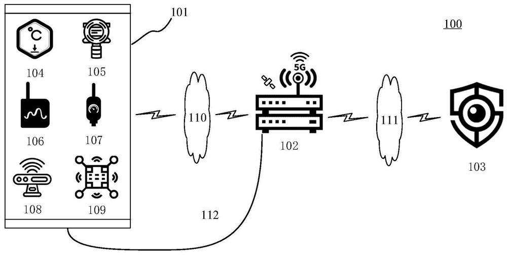
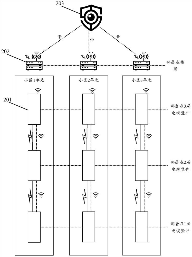
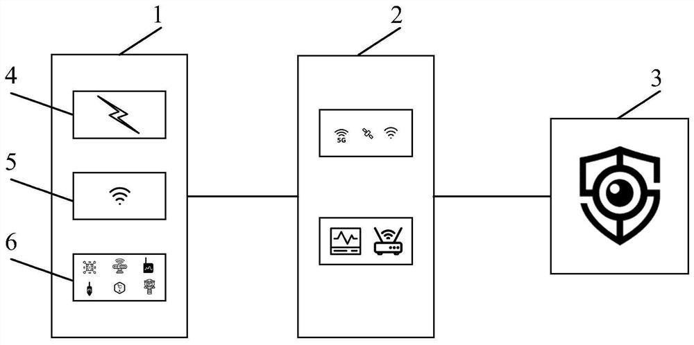
The embodiment of the invention discloses a cable shaft monitoring system, method and device. According to one specific embodiment, the system comprises a sensing node communication unit, a routing communication calculation unit and a safety center platform unit, and the sensing node communication unit is arranged in a cable shaft of each floor and used for collecting information in the cable shaft; the sensing node communication unit is in communication connection with the routing communication calculation unit and is also used for sending the acquired information in the cable shaft to the routing communication calculation unit; the routing communication calculation unit is arranged on a roof and is used for receiving information in the cable shaft and carrying out edge calculation processing on the information in the cable shaft; and the routing communication calculation unit is in communication connection with the security center platform unit and is used for sending the data subjected to edge calculation processing to the security center platform unit. According to the embodiment, the efficiency of monitoring the real-time information in the cable shaft is improved, so that thetime for passively discovering dangerous cases is shortened.

Description

technical field [0001] The embodiments of the present disclosure relate to the technical field of safety monitoring, and in particular to a cable shaft monitoring system, method and device. Background technique [0002] In recent years, various dangers have frequently occurred in high-rise buildings in domestic and foreign communities, and once a danger occurs, it will cause a large amount of property loss and casualties. At present, wireless sensors are used for real-time monitoring of cable shafts in high-rise direct-supply communities. [0003] However, the following technical problems may exist in the above-mentioned monitoring method: [0004] First, the signal of the wireless sensor in the cable shaft is poor, and the monitoring information cannot be fed back in time; [0005] Second, the traditional building inspection is usually carried out regularly by professional construction personnel, which cannot detect the structural information of the building in real time,...

Claims


Application Information

Patent Timeline
Patent Type & Authority Applications(China)
IPC IPC(8): G01D21/02H02J13/00
CPCG01D21/02H02J13/00007H02J13/00022H02J13/00026Y02E60/00Y04S40/121Y04S40/126
Inventor 沈汉坤李康杜德顺
Owner 北京风桥科技有限公司
Why Eureka
Try Eureka