Measurement method of weak mud pulse pressure wave under high standing pressure

A technology of mud pulse and measurement method, which is applied in the direction of pressure difference measurement, measurement, and measurement devices among multiple valves, to achieve accurate measurement, reduce bit error rate, and the effect of simple and reliable method

Active Publication Date: 2022-02-08
BC P INC CHINA NAT PETROLEUM CORP +1
View PDF6 Cites 0 Cited by
  • Summary
  • Abstract
  • Description
  • Claims
  • Application Information

AI Technical Summary

Problems solved by technology

[0005] The present invention provides a method for measuring weak mud pulse pressure waves under high vertical pressure, which overcomes the shortcomings of the above-mentioned prior art, and can effectively solve the problem that the existing measurement methods are difficult to measure very small pulse pressure under high static pressure question

Method used


Image

  • Measurement method of weak mud pulse pressure wave under high standing pressure
  • Measurement method of weak mud pulse pressure wave under high standing pressure
  • Measurement method of weak mud pulse pressure wave under high standing pressure

Examples


Embodiment 1

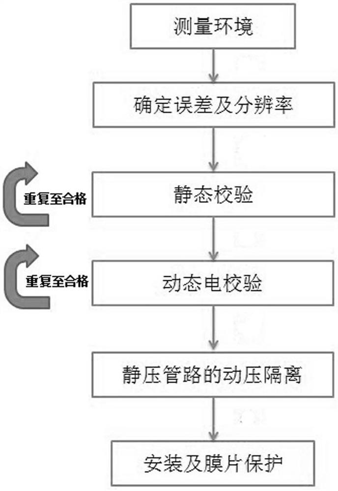
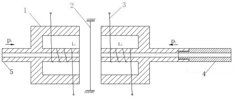
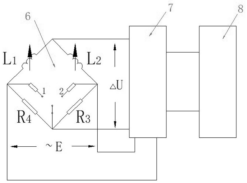
[0035] Embodiment 1: as attached Figures 1 to 3 As shown, the measurement method of the weak mud pulse pressure wave under high vertical pressure includes the following steps:

[0036] The first step: determine the error and resolution;

[0037] According to the measured mud pulse pressure amplitude, select a differential pressure sensor with appropriate range, error and resolution.

[0038] If the maximum amplitude of the measured mud pulse is 0.1MPa and the maximum allowable absolute error is 0.01MPa, the total accuracy of the measurement system is required to be better than 10%. If a differential pressure sensor with a total error of less than 5% is selected, the maximum allowable absolute error is 0.01MPa. It is required that the maximum range of the measurement system (differential pressure sensor) does not exceed 0.2MPa, so choosing a differential pressure sensor with a range of 0.1MPa to 0.2MPa can ensure the required measurement accuracy, and choosing a static range ...

Embodiment 2

[0058] Embodiment 2: Measurement environment: standpipe pressure 35 MPa, pulse signal pressure amplitude 0.5 MPa, ratio of dynamic pressure to static pressure 1.4%. The waveform of the dynamic pressure is as Figure 4 shown.

[0059] For this measurement environment, the measurement method of the weak mud pulse pressure wave under high vertical pressure includes the following steps:

[0060] (1) Determine the error and resolution

[0061] Using the error theory about the error relationship between the measuring tool and the detected object, the ratio of the random error of the measurement system to the fluctuation of the measured signal should be less than 1 / 3, that is, under the condition of 35MPa standpipe pressure, the total accuracy should be better than 1.4%×1 / 3=0.5%, the absolute error of measurement should not be greater than 0.5MPa×1 / 3=0.17MPa. The lowest measurable vibration level in the process of dynamic pressure measurement is when the signal-to-noise ratio is ...


PUM


Abstract

The invention relates to the technical field of a method for measuring information while drilling downhole oil and gas, and is a method for measuring weak mud pulse pressure waves under high vertical pressure, which includes determining error and resolution, static calibration, dynamic electrical calibration, static pressure There are six steps for pipeline dynamic pressure isolation, installation and diaphragm protection, and improvement of accuracy. The present invention can satisfy the extremely low-level dynamic pressure measurement under the high mud standpipe pressure, can withstand the high mud riser pressure, and has a wide range of dynamic pressure measurement; at the same time, it meets the extremely low-level measurement accuracy and avoids the strain type measurement method 1. Zero drift and working frequency interference problems of the piezoelectric measurement method; the method of the present invention can effectively adapt to the mud pulse signal measurement environment, accurately measure, significantly reduce the bit error rate, and has great practical value.

Description

technical field [0001] The invention relates to the technical field of a method for measuring downhole drilling information of oil and gas, and relates to a method for measuring weak mud pulse pressure waves under high standing pressure. Background technique [0002] The mud pulse pressure wave signal transmitted in the drill string is essentially generated by the compressibility of the mud, and the reliability of the monitoring and control data while drilling is based on the reliability of various measurement data. In the process of the mud pulse signal propagating along the mud medium in the drill string, the pulse signal is affected by various factors such as well depth, transmission frequency, mud density, friction resistance of the inner wall of the drill string, drilling pump pressure, etc., and its transmission process is a continuous attenuation. As a result, the amplitude of the pressure wave signal collected by the ground decoding system is small and the noise is l...

Claims


Application Information

Patent Timeline
Patent Type & Authority Patents(China)
IPC IPC(8): G01L27/00G01L13/02E21B47/06
CPCG01L27/005G01L13/025E21B47/06
Inventor 尚仓健伊明乔东宇赵继斌李富强张磊王飞跃孙鹏成攀飞
Owner BC P INC CHINA NAT PETROLEUM CORP
Why Eureka
Try Eureka