
Anti-torsion rotary spacer

A technology of rotary and spacer rods, which is applied to the installation of devices for maintaining the distance between parallel conductors, electrical components, and cables. It can solve the problems of increasing labor costs, time-consuming and laborious, and easy twisting of spacer rods to reduce maintenance costs. , easy to use, and avoid danger

Active Publication Date: 2021-02-23
GUIZHOU POWER GRID CO LTD
View PDF16 Cites 1 Cited by
  • Summary
  • Abstract
  • Description
  • Claims
  • Application Information

AI Technical Summary

Problems solved by technology

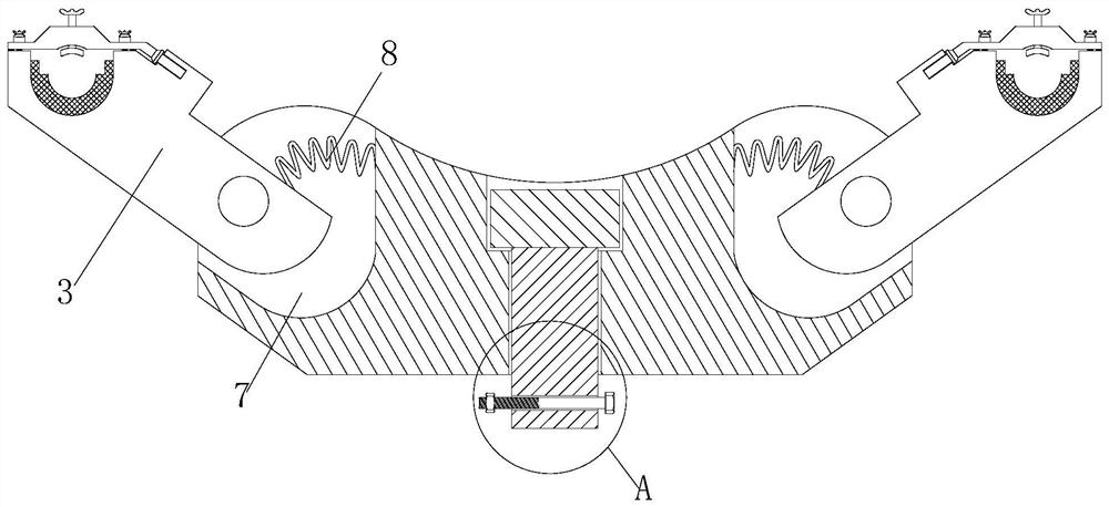
[0003] Existing spacers are easy to twist together when encountering strong winds, requiring manual adjustment by workers, which is time-consuming and labor-intensive, and increases labor costs

Method used

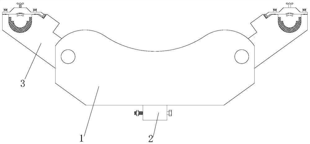

Image

  • Anti-torsion rotary spacer
  • Anti-torsion rotary spacer
  • Anti-torsion rotary spacer

Examples


Embodiment Construction

[0026] The following will clearly and completely describe the technical solutions in the embodiments of the present invention with reference to the accompanying drawings in the embodiments of the present invention. Obviously, the described embodiments are only some, not all, embodiments of the present invention.

[0027] Examples of the described embodiments are shown in the drawings, wherein like or similar reference numerals designate like or similar elements or elements having the same or similar functions throughout. The embodiments described below by referring to the figures are exemplary and are intended to explain the present invention and should not be construed as limiting the present invention.

[0028] In describing the present invention, it should be understood that the terms "center", "longitudinal", "transverse", "length", "width", "thickness", "upper", "lower", "front", " Back", "Left", "Right", "Vertical", "Horizontal", "Top", "Bottom", "Inner", "Outer", "Clock...


PUM


Abstract

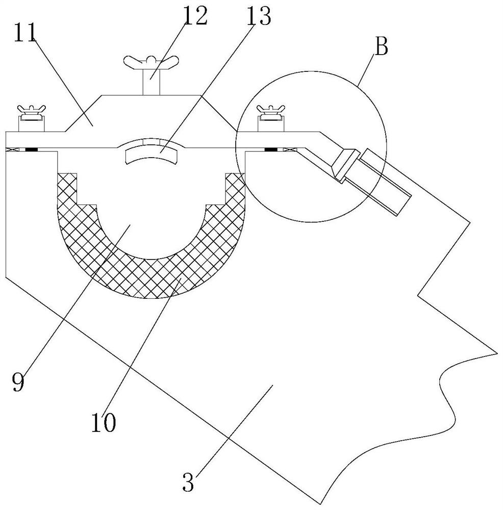
The invention discloses an anti-torsion rotary spacer. The spacer comprises a body, wire clamps are installed at the two ends of the body, a balancing weight is installed in the middle of the body, movable cavities are formed in the two ends of the body, one ends of the two wire clamps extend into the movable cavities, and compression springs are installed at the tops of the ends, close to the movable cavities, of the two wire clamps. The other ends of the compression springs are fixedly connected with the inner walls of the movable cavities, one end of each wire clamp is provided with a wiregroove, and the bottom of the inner wall of each wire groove is fixedly connected with an insulating cushion block. The balancing weight is arranged in the middle of the body, so that when the body isused, the gravity center can be kept at the position close to the lower portion of the middle, the compression springs are installed at one ends of the two wire clamps, the wire clamps can be kept atthe fixed positions all the time, and therefore the device is not prone to torsion.

Description

technical field [0001] The invention relates to the technical field of electric equipment, in particular to an anti-twist rotary spacer. Background technique [0002] The spacer bar refers to the fittings installed on the split wires to fix the distance between the split wires to prevent the wires from whipping each other, suppress the breeze vibration and the vibration of the sub-gap. The main requirement for the spacer bar is that the wire clamp must have sufficient grip , and it is not allowed to loosen during long-term operation, and the overall strength must be able to withstand the centripetal force of each split wire when the line is short-circuited and the fatigue under long-term vibration. The spacer can be divided into two categories: damping and rigidity in terms of performance. The damping spacer is embedded with a wear-resistant rubber pad in its moving parts, and uses the damping of the rubber pad to consume the vibration energy of the conductor, thereby produc...

Claims


Application Information

Patent Timeline
IPC IPC(8): H02G7/12
CPCH02G7/12H02G7/125
Inventor 徐梁刚杨承林冯文斌崔建
Owner GUIZHOU POWER GRID CO LTD
Learn More