
Antenna switching system and method, and storage medium

An antenna switching and antenna technology, applied in the field of mobile communication, can solve the problems of lack of directional antennas, difficulty, high cost, etc., and achieve the effects of reducing transmission power, reducing heat, and enhancing received signal strength

Pending Publication Date: 2021-02-23
ZTE CORP
View PDF0 Cites 6 Cited by
  • Summary
  • Abstract
  • Description
  • Claims
  • Application Information

AI Technical Summary

Problems solved by technology

[0003] Aiming at the lack of directional antennas in existing wireless communication terminals and the problems of difficult installation, maintenance and high cost, the present invention designs a method that can improve the high-gain characteristics of the antenna and improve the actual data throughput rate of the user, and does not require additional professional installation and installation by the user. easy to maintain

Method used


Image

  • Antenna switching system and method, and storage medium
  • Antenna switching system and method, and storage medium
  • Antenna switching system and method, and storage medium

Examples


Embodiment 1

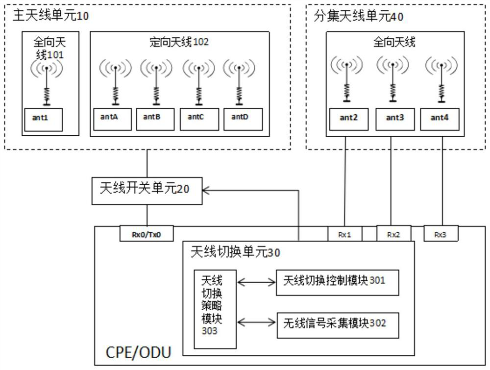
[0054] This embodiment is aimed at indoor wireless CPE products, outdoor ODU products and other terminals that complete communication with the base station through wireless transceivers. In this embodiment, the main antenna unit includes 1 omni-directional antenna and 4 high-gain directional antennas. Different high-gain directional Antennas can cover different angles. At present, directional antennas with 9dB gain are more commonly used, and the corresponding coverage angle is about 90 degrees. Therefore, 360-degree full coverage can be achieved by using 4 directional antennas. The schematic diagram of the antenna switching system is as follows image 3 shown.

[0055] This system mainly comprises main antenna unit 10, antenna switch unit 20, antenna switch unit 30, four parts of diversity antenna unit 40, and diversity antenna unit 40 is the original design of product, is not main content of the present invention.

[0056] Wherein, the main antenna unit 10 is used for recei...

Embodiment 2

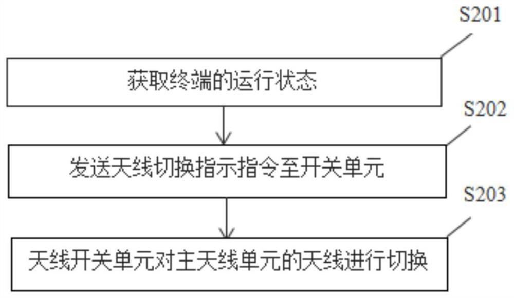
[0067] Figure 4 It is a work flow chart of an antenna switching method in the preferred embodiment 2 of the present invention. This embodiment provides a method for indoor wireless CPE products and outdoor ODU products to enhance the received signal strength through adaptive selection of antennas. This method is applied to the above-mentioned The antenna switching system specifically includes the following steps:

[0068] In step S401, the terminal registers with the wireless cellular network after it is turned on, and the registration process can be registered to the LTE standard or the NR standard.

[0069] Step S402, the antenna switching unit is started, and the antenna switching unit includes a wireless signal acquisition module, an antenna switching control module and an antenna switching strategy module.

[0070] In step S403, the antenna switching strategy module inquires about the registration status of the current wireless cellular network and the registered frequ...


PUM


Abstract

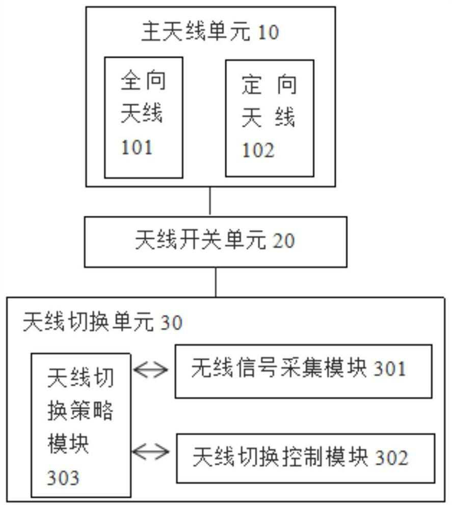
The invention provides an antenna switching system and method and a storage medium. The antenna switching system is used for the wireless communication terminal and comprises a main antenna unit, an antenna switch unit and an antenna switching unit, wherein the main antenna unit comprises an omnidirectional antenna and a directional antenna; the antenna switching unit comprises a wireless signal acquisition module, an antenna switching control module and an antenna switching strategy module; and the antenna switching strategy module is used for generating an indication instruction according tothe operation state of the terminal and controlling switching between the omnidirectional antenna and the directional antenna. Through the mode, the received signal strength of the wireless communication terminal can be enhanced, and the transmitting power of the terminal is reduced, so the throughput rate of user service data is improved, and the standby time of a product is prolonged.

Description

technical field [0001] The present invention relates to the technical field of mobile communication, in particular to an antenna switching system and method, and a storage medium. Background technique [0002] With the standardization of 5G technology and the development of chip manufacturers and terminal manufacturers, 5G products are getting closer and closer to us. The first scenario in the three major scenarios of 5G is enhanced mobile broadband eMBB (Enhanced MBB), bringing users higher data Throughput rate. This feature will be widely used by operators to deploy and replace existing fixed network products in the future. Customer Premise Equipment (CPE) in European and American markets will mainly be in the form of an outdoor unit ODU (Out Door Unit) Now, how to increase the antenna gain and the RSRP (Reference Signal Receiving Power) of the terminal in this scenario to increase the data throughput becomes particularly important. It is also one of the main competitive...

Claims


Application Information

Patent Timeline
Patent Type & Authority Applications(China)
IPC IPC(8): H04B7/06H04B7/08H04B17/327H04B17/382
CPCH04B7/061H04B7/082H04B17/327H04B17/382
Inventor 宋欣
Owner ZTE CORP
Learn More