Automatic iron sheet stamping equipment

A kind of stamping equipment and automatic technology, applied in the direction of pushing out equipment, metal processing equipment, feeding devices, etc., can solve the problem of inconvenient collection of stamped and formed iron sheets, and achieve the effect of convenient collection

Inactive Publication Date: 2021-02-26
赵勇
View PDF6 Cites 6 Cited by
  • Summary
  • Abstract
  • Description
  • Claims
  • Application Information

AI Technical Summary

Problems solved by technology

[0005] In order to overcome the shortcomings of the existing iron sheet stamping and forming method that the iron sheet needs to be manually moved, the iron sheet is manually stamped and formed, and the collection of the stamped and formed iron sheet is inconvenient, the technical problem of the present invention is to provide a method that can automatically align the iron sheet It is an automatic stamping equipment for iron sheets that performs blanking, automatically pushes iron sheets, automatically stamps and forms iron sheets, and facilitates people to collect the stamped and formed iron sheets

Method used


Image

  • Automatic iron sheet stamping equipment
  • Automatic iron sheet stamping equipment
  • Automatic iron sheet stamping equipment

Examples


Embodiment 1

[0026] A kind of iron sheet automatic stamping equipment, such as figure 1 and figure 2 As shown, it includes a bottom plate 1, a biaxial motor 2, a table 3, a pressing mechanism 4 and a pushing mechanism 5. A pressing mechanism 4 is provided on the middle side of the top, and the parts of the pressing mechanism 4 are connected with the output shaft of the biaxial motor 2. A pushing mechanism 5 is installed on the table 3, and the parts of the pushing mechanism 5 are connected with the parts of the pressing mechanism 4 .

[0027] When people need to automatically stamp the iron sheet, people first place the iron sheet on the parts of the pushing mechanism 5, and then people start the biaxial motor 2, and the rotation of the parts of the biaxial motor 2 drives the rotation of the parts of the pressing mechanism 4, The rotation of the parts of the pressing mechanism 4 drives the parts of the pressing mechanism 4 to move up and down, and the parts of the pressing mechanism 4 m...

Embodiment 2

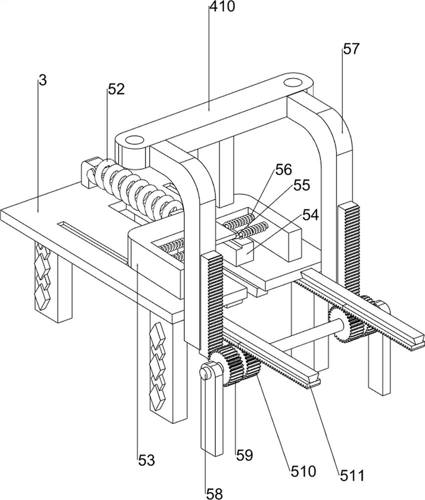
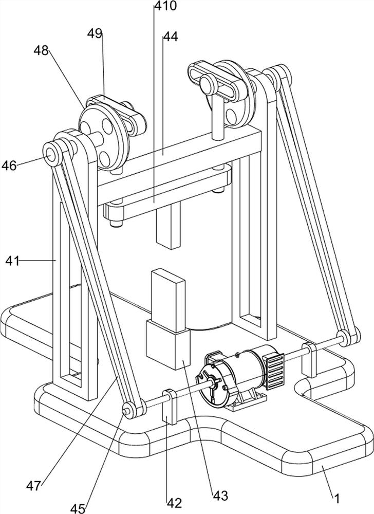
[0029] On the basis of Example 1, such as image 3 , Figure 4 and Figure 5 As shown, the pressing mechanism 4 includes a first support frame 41, a second support frame 42, a shrink frame 43, a first fixed rod 44, a first rotating shaft 45, a second rotating shaft 46, a belt assembly 47, and a disc 48 , the pressing push rod 49 and the stamping sheet 410, the first support frame 41 is provided on the left and right sides of the top of the bottom plate 1, the second support frame 42 is provided on the left and right sides of the top of the front side of the bottom plate 1, and the middle of the top of the bottom plate 1 is provided with a shrink Frame 43, the first support frame 41 is slidingly connected with the first fixed rod 44, the output shaft of the biaxial motor 2 is provided with the first rotating shaft 45, and the first rotating shaft 45 passes through the second supporting frame 42 , the upper part of the first support frame 41 is rotatably connected with a secon...

Embodiment 3

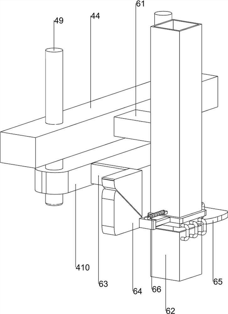
[0034] On the basis of Example 2, such as Figure 6 , Figure 7 and Figure 8 As shown, a blanking mechanism 6 is also included, and the blanking mechanism 6 includes a second fixed rod 61, a blanking plate 62, a first wedge block 63, a second wedge block 64, a material blocking plate 65 and a second tension spring 66 , the middle part of the rear side of the first fixed rod 44 is provided with a second fixed rod 61, the rear part of the second fixed rod 61 is connected with a blanking plate 62, and the right side of the stamping sheet 410 rear portion is provided with a first wedge-shaped block 63, and the blanking plate 62 The lower side is slidingly connected with a material stopper 65, and the right part of the material stopper 65 is connected with a second wedge-shaped block 64, and the second wedge-shaped block 64 is squeeze-fitted with the first wedge-shaped block 63, and the second wedge-shaped block 64 is connected with the blanking plate 62. A second tension spring...


PUM


Abstract

The invention relates to automatic stamping equipment, in particular to automatic iron sheet stamping equipment. According to the automatic iron sheet stamping equipment, iron sheets can be automatically blanked, pushed and stamped, and people can conveniently collect the stamped iron sheets. The automatic iron sheet stamping equipment comprises a bottom plate, a table, a material pressing mechanism and a material pushing mechanism, wherein a double-shaft motor is arranged on one side of the top of the bottom plate, the table is arranged on the side, away from the double-shaft motor, of the top of the bottom plate, the material pressing mechanism is arranged on the side, close to the double-shaft motor, of the top of the bottom plate, parts of the material pressing mechanism are connectedto an output shaft of the double-shaft motor, and the material pushing mechanism is installed on the table. Under the cooperation of the double-shaft motor, the material pressing mechanism, the material pushing mechanism, the blanking mechanism, the discharging mechanism and a clamping mechanism, the effects of blanking the iron sheets, automatically pushing the iron sheets, carrying out stampingon the iron sheets and facilitating collection of the iron sheets subjected to stamping by people can be achieved.

Description

technical field [0001] The invention relates to an automatic stamping equipment, in particular to an automatic stamping equipment for iron sheets. Background technique [0002] Iron sheet is a kind of part that is often used in industry. Before the iron sheet is put into use, people generally need to stamp it. [0003] The existing iron sheet stamping method is generally to manually stamp and form the iron sheet. People first place the iron sheet under the stamping device, and then people start the stamping device to stamp the iron sheet. After the iron sheet stamping is completed, people Then the iron sheets that have been stamped and formed are collected. The method of stamping and forming the iron sheets is cumbersome. It is necessary to manually place the iron sheets one by one under the stamping device, and it is inconvenient to collect the stamped and formed iron sheets. [0004] Therefore, it is necessary to develop an automatic stamping equipment for iron sheets tha...

Claims


Application Information

Patent Timeline
Patent Type & Authority Applications(China)
IPC IPC(8): B21D22/02B21D43/04B21D45/04B21D43/20
CPCB21D22/02B21D43/04B21D45/04B21D43/20
Inventor 赵勇
Owner 赵勇
Why Eureka
Try Eureka