Mechanical automatic cutting device
A cutting device and mechanical technology, which is applied in the direction of shearing device, shearing machine accessory device, metal processing equipment, etc., can solve the problems that the accurate length of feeding cannot be guaranteed, the steel plate is difficult to unify the quality of the steel plate, and the parts are damaged, so as to save the cost of cutting time, reduce labor intensity, and ensure safety
- Summary
- Abstract
- Description
- Claims
- Application Information
AI Technical Summary
Problems solved by technology
Method used
Image
Examples
Embodiment 1
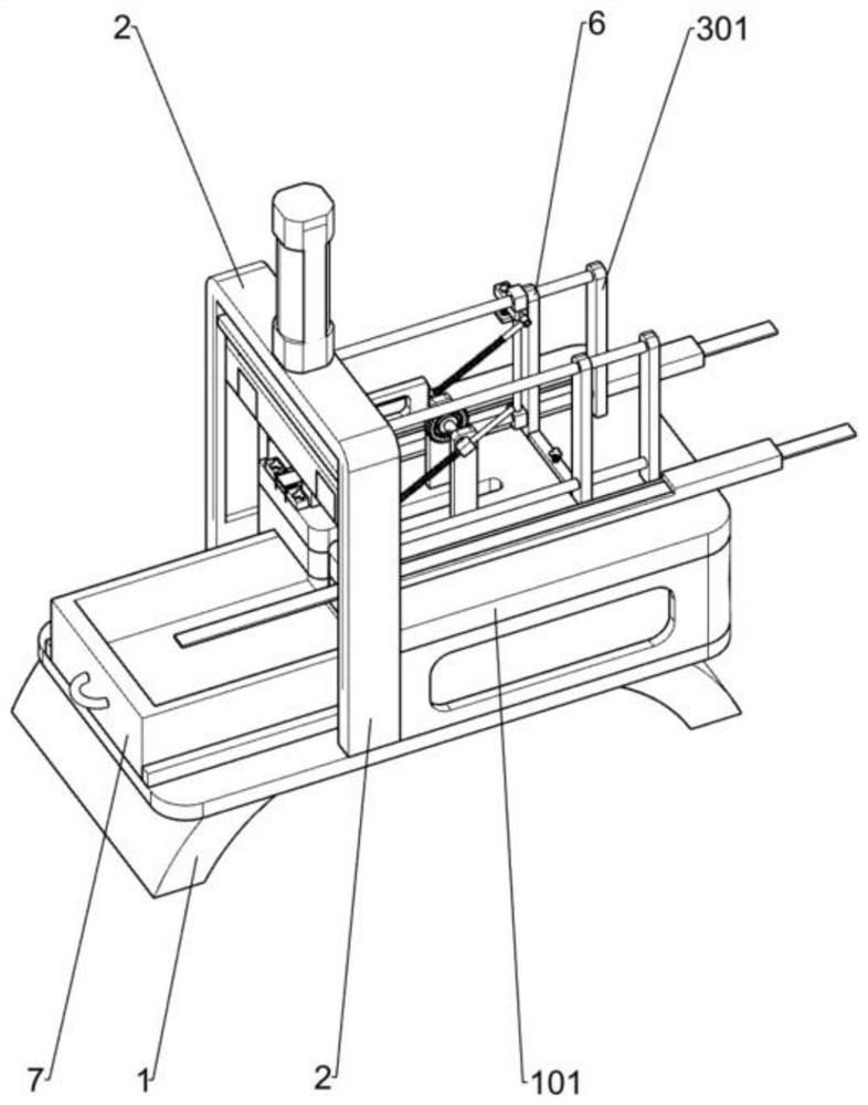
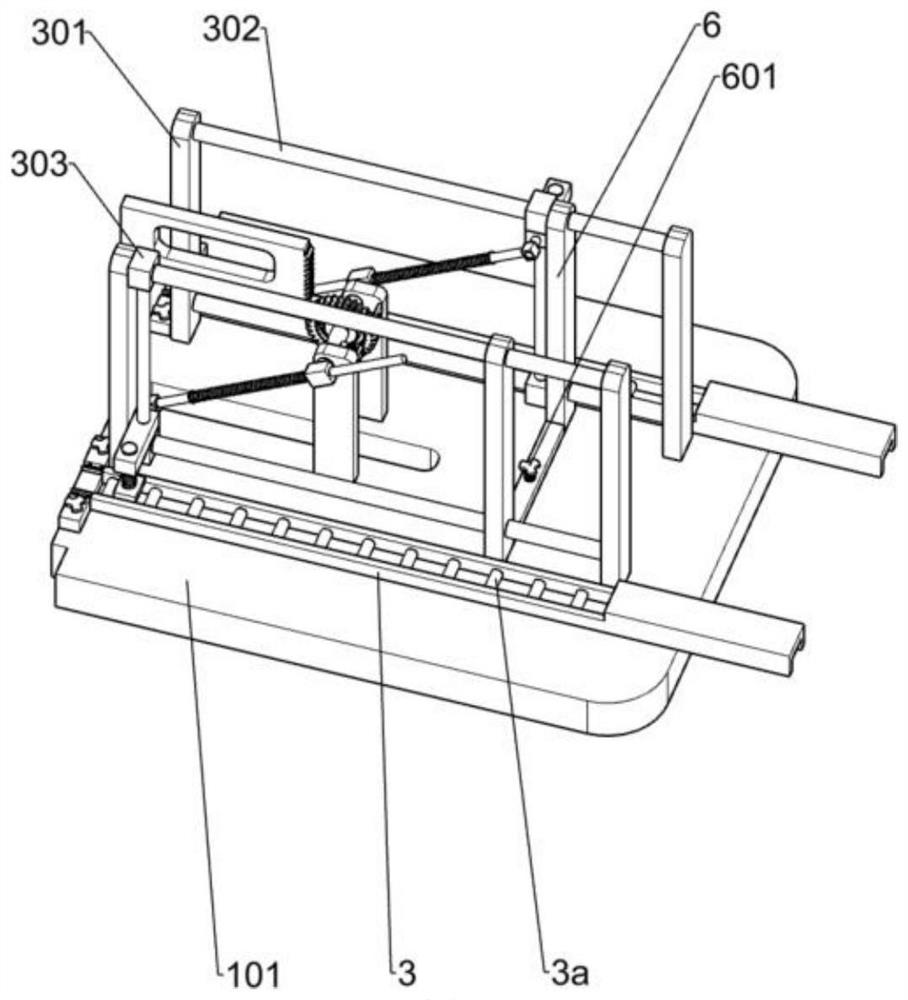
[0028] A mechanical automatic cutting device, such as Figure 1-5 As shown, it includes a support 1, a workbench 101, a cutting mechanism, a feeding mechanism and a material box 7. The workbench 101 is fixedly installed on the upper right side of the support 1, and the cutting mechanism is fixedly installed in the middle of the support 1. The cutting mechanism is located at the workbench 101 On the left side, the feeding mechanism is fixedly installed on the workbench 101, and the material box 7 is fixedly installed on the left side of the support 1.
[0029] When starting the device, manually put the plate to be cut off into the feeding mechanism, start the cutting mechanism, and at the same time the cutting mechanism moves downward, feed the material to the bottom of the cutting mechanism with the feeding mechanism, after the cutting mechanism cuts off the steel plate, the steel plate closes Deadweight falls in the feed box 7 and collects.
Embodiment 2
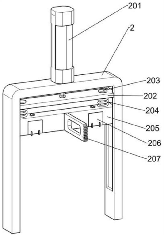
[0031] On the basis of Example 1, such as figure 2 As shown, the truncation mechanism includes a support frame 2, a cylinder 201, a first pressure plate 205, a truncation block 206, a gear bar 207 and a buffer mechanism. The upper part of the buffer mechanism is fixedly installed on the telescopic rod of the cylinder 201, the buffer mechanism is slidingly connected with the inner side of the support frame 2, the first pressure plate 205 is fixedly installed on the lower side of the buffer mechanism, and the first pressure plate 205 is connected with the inside of the support frame 2. The two sides are slidably connected, the two truncated blocks 206 are fixedly installed on the lower side of the first pressing plate 205 , and the gear bar 207 is fixedly installed on the middle position on the left side of the first pressing plate 205 .
[0032] Start the cylinder 201, the telescopic rod of the cylinder 201 moves downward with the buffer mechanism, the buffer mechanism presses...
Embodiment 3
[0040] On the basis of Example 2, such as Figure 6 As shown, a clamping mechanism is also included. The clamping mechanism includes a fixed plate 5, a second slide plate 501, a third sliding column 502 and a tension spring 503. The two fixed plates 5 are fixedly installed on the upper left part of the workbench 101. Two pairs of third sliding columns 502 are slidably installed on the inner side of the fixed plate 5, each second sliding plate 501 is fixedly installed on the inner ends of two third sliding columns 502, and the tension spring 503 is sleeved on the third sliding column. 502 on.
[0041] After the feeding mechanism finishes feeding, when the cutting mechanism is ready to cut off, before the cutting block 206 on the first pressing plate 205 touches the steel plate, the raised part on the cutting block 206 first squeezes the slide plate inwardly, and now the tension spring 503 is in the power storage state. state, the steel plate is clamped, and after the truncatio...
PUM
 Abstract
Description
Claims
Application Information
 - R&D
- Intellectual Property
- Life Sciences
- Materials
- Tech Scout
- Unparalleled Data Quality
- Higher Quality Content
- 60% Fewer Hallucinations
Browse by: Latest US Patents, China's latest patents, Technical Efficacy Thesaurus, Application Domain, Technology Topic, Popular Technical Reports.
© 2025 PatSnap. All rights reserved.Legal|Privacy policy|Modern Slavery Act Transparency Statement|Sitemap|About US| Contact US: help@patsnap.com


