A mechanical automatic cut-off device

A cutting device and mechanical technology, applied in shearing devices, accessories of shearing machines, metal processing equipment, etc., can solve the problems of inability to guarantee the exact length of feeding, difficulty in unifying the quality of steel plates, and damage to parts, etc., to save cutting time. Time, reduce labor intensity, and ensure the effect of safety

Active Publication Date: 2022-03-01
福建省嘉泰智能装备有限公司
View PDF8 Cites 0 Cited by
  • Summary
  • Abstract
  • Description
  • Claims
  • Application Information

AI Technical Summary

Problems solved by technology

[0005] In order to overcome the shortcomings of manual feeding, the precise length of the feeding cannot be guaranteed, the length of the truncated steel plates is different, it is difficult to unify the quality of the steel plates, and the parts in the equipment are damaged and difficult to replace. The technical problems to be solved are: to provide a An automatic cutting device for strip-shaped steel plates that realizes automatic feeding and whose cutting length can be adjusted

Method used


Image

  • A mechanical automatic cut-off device
  • A mechanical automatic cut-off device
  • A mechanical automatic cut-off device

Examples


Embodiment 1

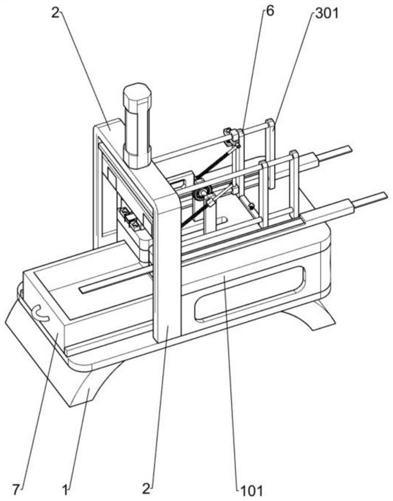
[0028] A mechanical automatic cutting device, such as Figure 1-5 As shown, it includes a support 1, a workbench 101, a cutting mechanism, a feeding mechanism and a material box 7. The workbench 101 is fixedly installed on the upper right side of the support 1, and the cutting mechanism is fixedly installed in the middle of the support 1. The cutting mechanism is located at the workbench 101 On the left side, the feeding mechanism is fixedly installed on the workbench 101, and the material box 7 is fixedly installed on the left side of the support 1.

[0029] When starting the device, manually put the plate to be cut off into the feeding mechanism, start the cutting mechanism, and at the same time the cutting mechanism moves downward, feed the material to the bottom of the cutting mechanism with the feeding mechanism, after the cutting mechanism cuts off the steel plate, the steel plate closes Deadweight falls in the feed box 7 and collects.

Embodiment 2

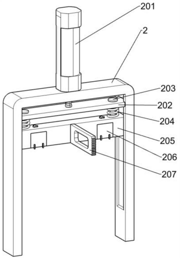
[0031] On the basis of Example 1, such as figure 2 As shown, the truncation mechanism includes a support frame 2, a cylinder 201, a first pressure plate 205, a truncation block 206, a gear bar 207 and a buffer mechanism. The upper part of the buffer mechanism is fixedly installed on the telescopic rod of the cylinder 201, the buffer mechanism is slidingly connected with the inner side of the support frame 2, the first pressure plate 205 is fixedly installed on the lower side of the buffer mechanism, and the first pressure plate 205 is connected with the inside of the support frame 2. The two sides are slidably connected, the two truncated blocks 206 are fixedly installed on the lower side of the first pressing plate 205 , and the gear bar 207 is fixedly installed on the middle position on the left side of the first pressing plate 205 .

[0032] Start the cylinder 201, the telescopic rod of the cylinder 201 moves downward with the buffer mechanism, the buffer mechanism presses...

Embodiment 3

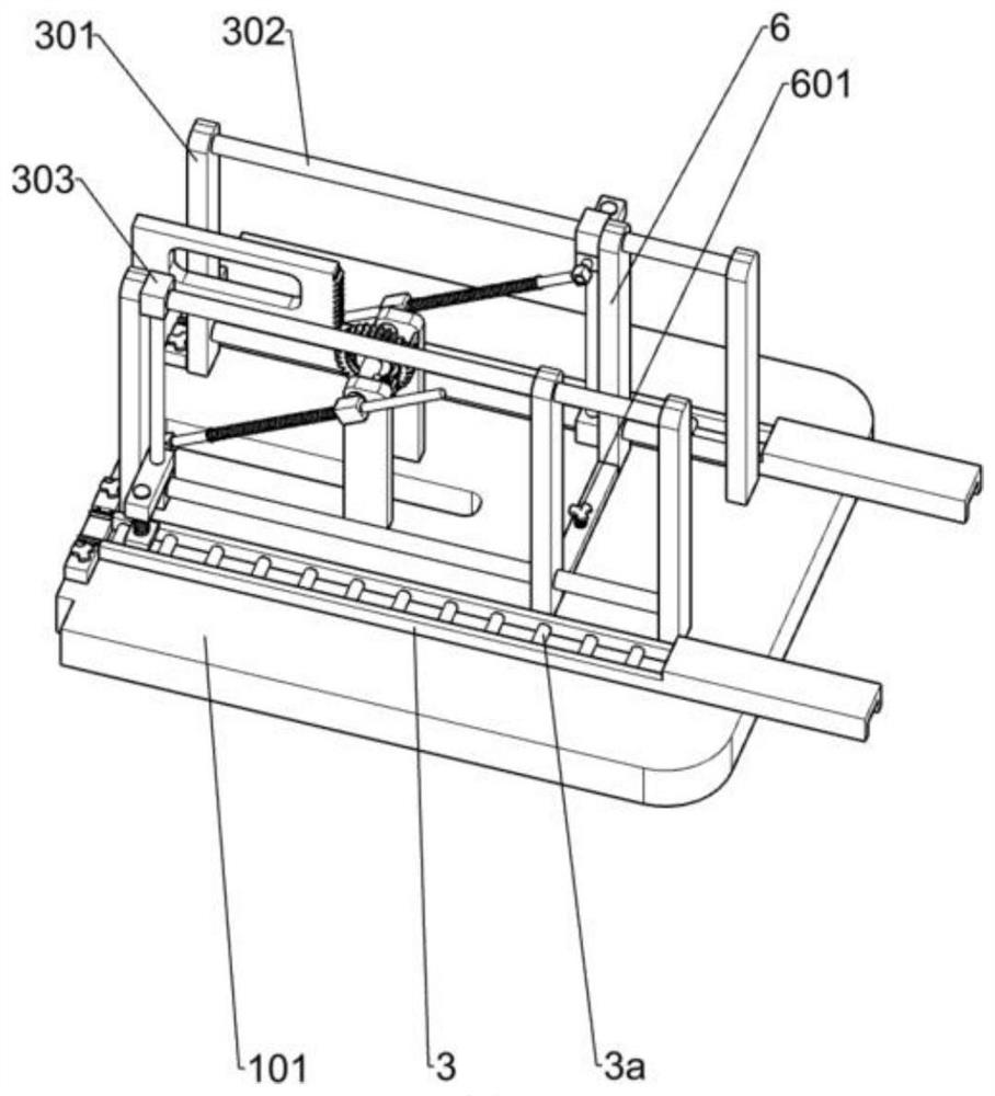
[0040] On the basis of Example 2, such as Figure 6 As shown, a clamping mechanism is also included. The clamping mechanism includes a fixed plate 5, a second slide plate 501, a third sliding column 502 and a tension spring 503. The two fixed plates 5 are fixedly installed on the upper left part of the workbench 101. Two pairs of third sliding columns 502 are slidably installed on the inner side of the fixed plate 5, each second sliding plate 501 is fixedly installed on the inner ends of two third sliding columns 502, and the tension spring 503 is sleeved on the third sliding column. 502 on.

[0041] After the feeding mechanism finishes feeding, when the cutting mechanism is ready to cut off, before the cutting block 206 on the first pressing plate 205 touches the steel plate, the raised part on the cutting block 206 first squeezes the slide plate inwardly, and now the tension spring 503 is in the power storage state. state, the steel plate is clamped, and after the truncatio...


PUM


Abstract

The invention relates to a cutting device, in particular to a mechanical automatic cutting device. The technical problem to be solved is to provide an automatic cutting device for strip-shaped steel plates which realizes automatic feeding and whose cutting length of steel plates can be adjusted. The technical scheme of the present invention is a mechanical automatic cutting device, including brackets, etc.; a cutting mechanism, a feeding mechanism and a material box, one side of the workbench is fixedly installed on the bracket, the cutting is fixed and installed in the middle of the nail, and the cutting mechanism is located on the workbench. One side, the feeding mechanism is fixedly installed on the workbench, and the material box is fixedly installed on the side of the bracket close to the workbench. The present invention adds a feeding mechanism, which realizes alternate feeding processes, saves the cutting time of the steel plate, and improves the overall production efficiency of the device.

Description

technical field [0001] The invention relates to a cutting device, in particular to a mechanical automatic cutting device. Background technique [0002] The steel plate is a flat steel material that is poured with molten steel and pressed after cooling. It is flat and rectangular, and can be directly rolled or cut from a wide steel strip. [0003] The traditional cutting process of the steel plate is to manually put the steel material to be cut off on the stamping mechanism, use the half-cut to pinch the steel plate, manually collect the cut steel material, and then carry out the next stage of feeding, but when feeding manually , the exact length of the feeding cannot be guaranteed, the length of the truncated steel plates is different, it is difficult to unify the quality of the steel plates, and the weight of the steel plates is relatively heavy. When collecting manually, a lot of manpower is wasted, the labor intensity of the workers is increased, and the production effici...

Claims


Application Information

Patent Timeline
Patent Type & Authority Patents(China)
IPC IPC(8): B23D31/00B23D33/02
CPCB23D31/002B23D33/02
Inventor 贾素平
Owner 福建省嘉泰智能装备有限公司
Why Eureka
Try Eureka