
Lens group manufacturing method, lens group, lens, imaging module and electronic device

A manufacturing method and lens group technology, applied in the field of optical imaging, can solve the problems of high manufacturing cost, easy generation of bubbles, easy degumming, etc., and achieve the effects of reducing manufacturing processes, improving yield rate, and reducing manufacturing costs

Active Publication Date: 2021-02-26
OPPO CHONGQING INTELLIGENT TECH CO LTD
View PDF16 Cites 0 Cited by
  • Summary
  • Abstract
  • Description
  • Claims
  • Application Information

AI Technical Summary

Problems solved by technology

However, using the optical glue method, the center error of the lens is not easy to guarantee, and bubbles are easy to be generated between the lenses, and it is easy to degumming. Most of them require a relatively complicated curing process and supporting equipment, such as ultraviolet lasers, heating ovens, etc., and the manufacturing cost is high. At the same time, when using the optical glue method, the optical lens will be required to have a very high processing accuracy, which will greatly increase the manufacturing cost of the optical lens

Method used


Image

  • Lens group manufacturing method, lens group, lens, imaging module and electronic device
  • Lens group manufacturing method, lens group, lens, imaging module and electronic device
  • Lens group manufacturing method, lens group, lens, imaging module and electronic device

Examples


Embodiment Construction

[0033] Embodiments of the present application are described in detail below, examples of which are shown in the drawings, wherein the same or similar reference numerals denote the same or similar elements or elements having the same or similar functions throughout. The embodiments described below by referring to the figures are exemplary, are only for explaining the present application, and should not be construed as limiting the present application.

[0034] In the present invention, unless otherwise clearly specified and limited, a first feature being "on" or "under" a second feature may include direct contact between the first and second features, and may also include the first and second features Not in direct contact but through another characteristic contact between them. Moreover, "above", "above" and "above" the first feature on the second feature include that the first feature is directly above and obliquely above the second feature, or simply means that the first fea...


PUM


Abstract

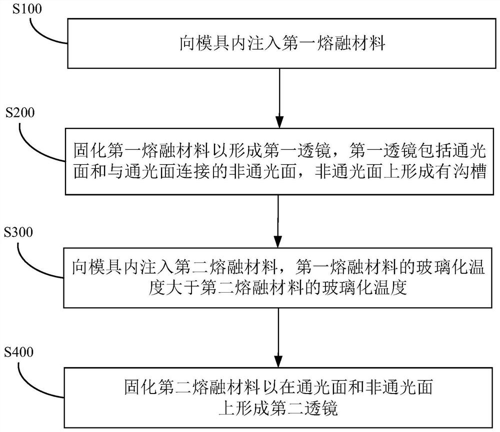
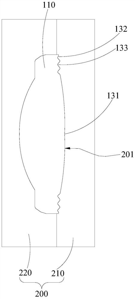
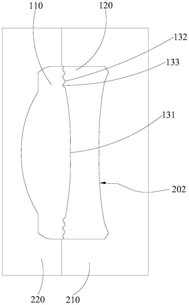
The invention discloses a lens group manufacturing method, a lens group, a lens, an imaging module and an electronic device. The lens group manufacturing method comprises the following steps that a first molten material is injected into a mold; the first molten material is cured to form a first lens, the first lens comprising a light-transmitting surface and a non-light-transmitting surface connected with the light-transmitting surface, and a groove is formed in the non-light-transmitting surface; a second molten material is injected into the mold, wherein the glass transition temperature of the first molten material is higher than that of the second molten material; and the second molten material is cured to form a second lens on the light-transmitting surface and the non-light-transmitting surface. Therefore, the two lenses are directly molded at one time to form the lens group, and the two lenses do not need to be separately formed and then glued, so that the manufacturing procedures are reduced, and the manufacturing cost is reduced. And meanwhile, one optical curved surface is shared, so that tolerance accumulation of primary optical surface eccentricity is reduced, poor lensfunction of the double-separation lens due to later lens assembly tolerance is avoided, and the yield of the lens is improved.

Description

technical field [0001] The present application relates to the technical field of optical imaging, and more specifically, relates to a manufacturing method of a lens set, a lens set, a lens, an imaging module, and an electronic device. Background technique [0002] In related technologies, in order to meet the requirements of increasing transmittance, eliminating chromatic aberration, and reducing the processing difficulty of complex optical lenses, imaging optical lenses often glue two or more lenses together, such as using optical glue and optical glue. Law. However, using the optical glue method, the center error of the lens is not easy to guarantee, and bubbles are easy to be generated between the lenses, and it is easy to degumming. Most of them require a relatively complicated curing process and supporting equipment, such as ultraviolet lasers, heating ovens, etc., and the manufacturing cost is high. At the same time, when the photoresist method is used, the optical le...

Claims


Application Information

Patent Timeline
Patent Type & Authority Applications(China)
IPC IPC(8): B29C45/16G02B13/00B29L11/00
CPCB29C45/1615G02B13/006B29L2011/0016
Inventor 袁正超
Owner OPPO CHONGQING INTELLIGENT TECH CO LTD
Learn More