Novel efficient green printing equipment

A kind of printing equipment and high-efficiency technology, applied in the field of new high-efficiency green printing equipment, can solve the problems of labor-intensive, low-efficiency green printing, manual replacement of printed items, etc., and achieve the effect of improving replacement efficiency

Active Publication Date: 2021-02-26
深圳市天亮环保科技有限公司
View PDF11 Cites 1 Cited by
  • Summary
  • Abstract
  • Description
  • Claims
  • Application Information

AI Technical Summary

Problems solved by technology

[0005] In order to overcome the low efficiency of manual green printing by workers, and the cumbersome process that workers need to manually replace the printed items every time, and after the items are printed, it takes a lot of effort for the workers to brush the green material on the items evenly, The technical problem is: to provide a new type of high-efficiency green printing equipment that can automatically replace printed items, and at the same time perform printing and pressing work on the items, and can evenly brush the materials on the items

Method used


Image

  • Novel efficient green printing equipment
  • Novel efficient green printing equipment
  • Novel efficient green printing equipment

Examples


Embodiment 1

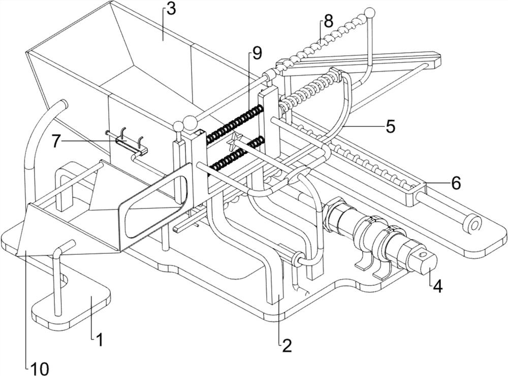
[0060] A new type of high-efficiency green printing equipment, such as figure 1 As shown, it includes a base plate 1, a first support seat 2, a discharge frame 3, a stamping mechanism 4 and a material pushing mechanism 5, the top of the base plate 1 is symmetrically provided with the first support seat 2 on the front and rear sides, and the first support seats 2 on the front and rear sides are symmetrical. A discharge frame 3 is connected between the support bases 2, and a stamping mechanism 4 is provided on the top front side of the bottom plate 1. The stamping mechanism 4 contacts and cooperates with the front side of the discharge frame 3, and the front side of the discharge frame 3 is slidingly provided with a pusher. Agency 5.

[0061]When the worker needs to carry out green printing on the item, the worker needs to put the item into the discharge frame 3 first, because the rear side of the discharge frame 3 is inclined, and the items on the rear side of the discharge fra...

Embodiment 2

[0063] In a preferred embodiment of the present invention, as figure 2 As shown, the stamping mechanism 4 includes a second support seat 41, a cylinder 42, a first push rod 43, a third support seat 44, a second push rod 45, a first support slide bar 46 and a stamp 47. The bottom plate 1 top The front side is provided with a second support seat 41, and a cylinder 42 is placed in the second support seat 41. The end of the telescopic rod of the cylinder 42 is fixedly connected with a first push rod 43, and a third support seat is installed on the left side of the top front side of the bottom plate 1. 44. The second push rod 45 is slidingly provided in the third support seat 44, the rear end of the first push rod 43 is connected to the middle part of the rear side of the second push rod 45, and the first support slide is connected between the front sides of the discharge frame 3. Rod 46, the front side sliding type of the second push rod 45 is located in the first support slide r...

Embodiment 3

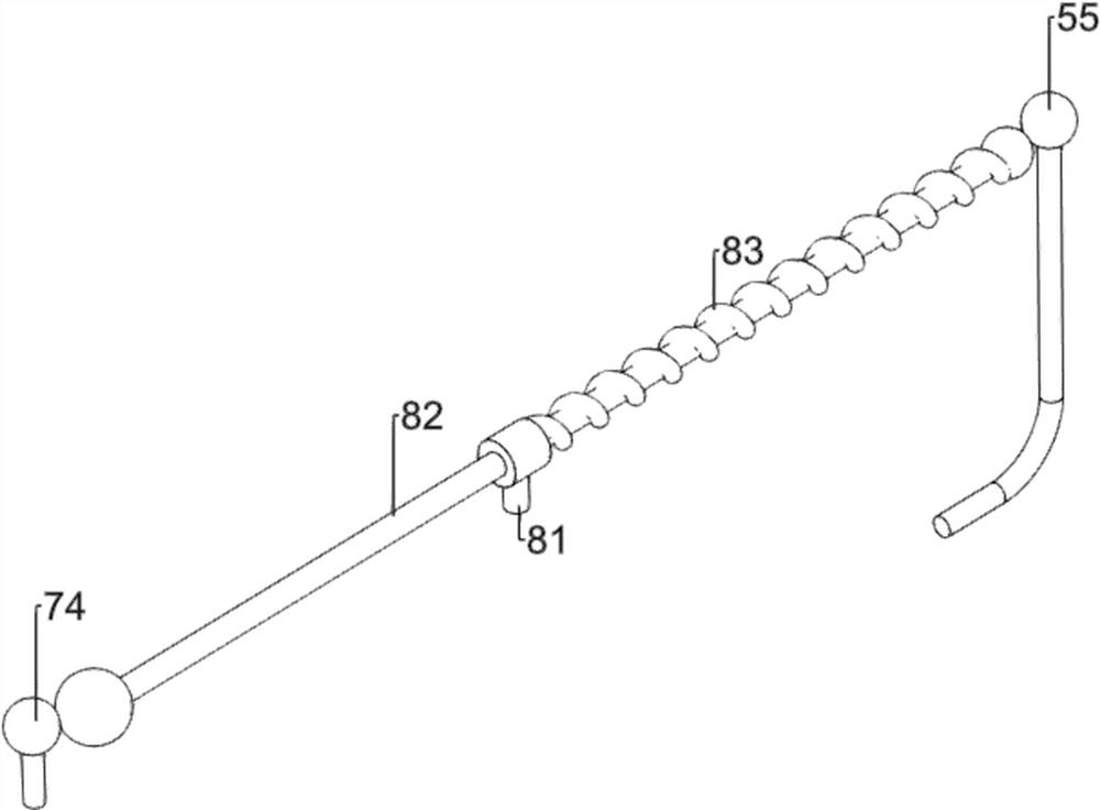
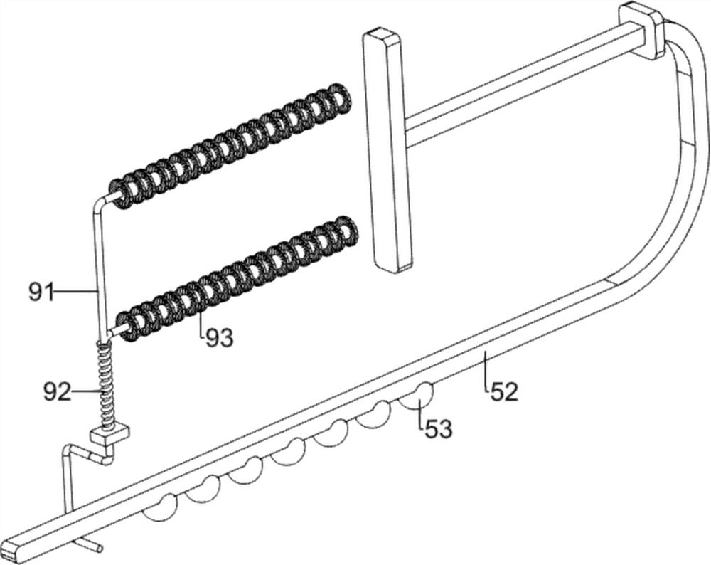
[0066] In a preferred embodiment of the present invention, as figure 1 and Figure 3-Figure 8 As shown, the pusher mechanism 5 includes a fourth support seat 51, a first push block 52, a small iron ball 53, a first spring 54, a first club 55 and a first long iron bar 56, and the discharge frame 3 right The front part of the side is fixedly connected with a fourth support seat 51, and the fourth support seat 51 is provided with a first push block 52 in a sliding manner, and the lower part of the first push block 52 is welded with small iron balls 53 at intervals, and the first push block 52 is sleeved with The first spring 54, the two ends of the first spring 54 are respectively connected on the fourth supporting seat 51 and the first pushing block 52, the first ball rod 55 is welded on the upper right end of the first pushing block 52, the lower part of the right end of the first pushing block 52 A first long iron bar 56 is provided.

[0067] When the first printed item on t...


PUM


Abstract

The invention relates to printing equipment, in particular to novel efficient green printing equipment. According to the novel efficient green printing equipment, printed objects can be automaticallyreplaced, meanwhile, the objects can be subjected to coining work, and materials can be evenly brushed on the objects. The novel efficient green printing equipment comprises a bottom plate, four firstsupporting seats and a discharging frame, and the four first supporting seats are symmetrically arranged on the two sides of the top of the bottom plate; and the discharging frame is connected between the first supporting seats on the two sides. According to the novel efficient green printing equipment, through the arrangement of a coining mechanism, the coining mechanism is matched with a pushing mechanism, and printing and replacing work of objects can be achieved; a pushing auxiliary mechanism is matched with the pushing mechanism, so that a worker does not need to manually push a first pushing block to the left side, and the object replacement efficiency is improved; and an opening and closing mechanism is matched with the pushing mechanism, a second ball rod can be automatically pushed backwards, and opening and closing of an opening and closing device do not need to be manually controlled by workers.

Description

technical field [0001] The invention relates to a printing device, in particular to a novel high-efficiency green printing device. Background technique [0002] Green printing refers to the use of environmentally friendly materials and processes. The printing process produces less pollution, saves resources and energy. After the printed matter is discarded, it is easy to recycle and recycle, can be naturally degraded, and has little impact on the ecological environment. Green printing is done manually by workers. The efficiency is low, and at the same time, the process for workers to manually replace the printed items every time is cumbersome, and after the items are printed, it takes a lot of effort for the workers to brush the green material on the items evenly. [0003] Patent application number CN211159147U discloses a new type of green printing device, including a support pedal, a support column, a pedal rod, a motor base, a drive motor, a retractable printing odor filt...

Claims


Application Information

Patent Timeline
Patent Type & Authority Applications(China)
IPC IPC(8): B41K3/00B41K3/48B41K3/62
CPCB41K3/00B41K3/48B41K3/62Y02P70/10
Inventor 呙四旭
Owner 深圳市天亮环保科技有限公司
Why Eureka
Try Eureka