
Flapping rotor wing device capable of ascending, half-rotating and descending

A flapping rotor, horizontal technology, applied in the field of aircraft, can solve the problems of high cost, complex structure, poor stability, etc., and achieve the effect of easy operation, reasonable design and convenient control

Inactive Publication Date: 2021-02-26
GUANGDONG GUOSHIJIAN TECH DEV CO LTD
View PDF4 Cites 1 Cited by
  • Summary
  • Abstract
  • Description
  • Claims
  • Application Information

AI Technical Summary

Problems solved by technology

[0003] In recent years, although there have been some technologies that combine flapping wings and rotors, that is, by using the flexible deformation of the flapping wings, the upward lift and forward thrust are generated when the flapping wings flap, and the antisymmetrical thrust forms a force couple at the same time, driving The flapping wing performs self-driven rotation, and the circumferential motion speed generated by the rotation can increase the lift, so as to achieve the purpose of increasing the overall lift. However, it has been found through experiments that the current flapping rotor device cannot provide enough lift for the aircraft. The ratio to the weight of the structure is very low, and the ability to take off normally has not been achieved
It can be seen that the existing flapping rotor devices often have disadvantages such as complex structure, bulky body, poor stability, difficult manufacturing design and high cost. These technical defects greatly limit the rapid development of flapping rotor devices

Method used


Image

  • Flapping rotor wing device capable of ascending, half-rotating and descending
  • Flapping rotor wing device capable of ascending, half-rotating and descending
  • Flapping rotor wing device capable of ascending, half-rotating and descending

Examples


Embodiment Construction

[0041] Embodiments of the present invention are described in detail below, examples of which are shown in the drawings, wherein the same or similar reference numerals designate the same or similar elements or elements having the same or similar functions throughout. The embodiments described below by referring to the figures are exemplary and are intended to explain the present invention and should not be construed as limiting the present invention.

[0042] In describing the present invention, it is to be understood that the terms "upper", "lower", "front", "rear", "left", "right", "vertical", "horizontal", "top", The orientation or positional relationship indicated by "bottom", "inner", "outer", etc. is based on the orientation or positional relationship shown in the drawings, and is only for the convenience of describing the present invention and simplifying the description, rather than indicating or implying the referred device or positional relationship. Elements must hav...


PUM


Abstract

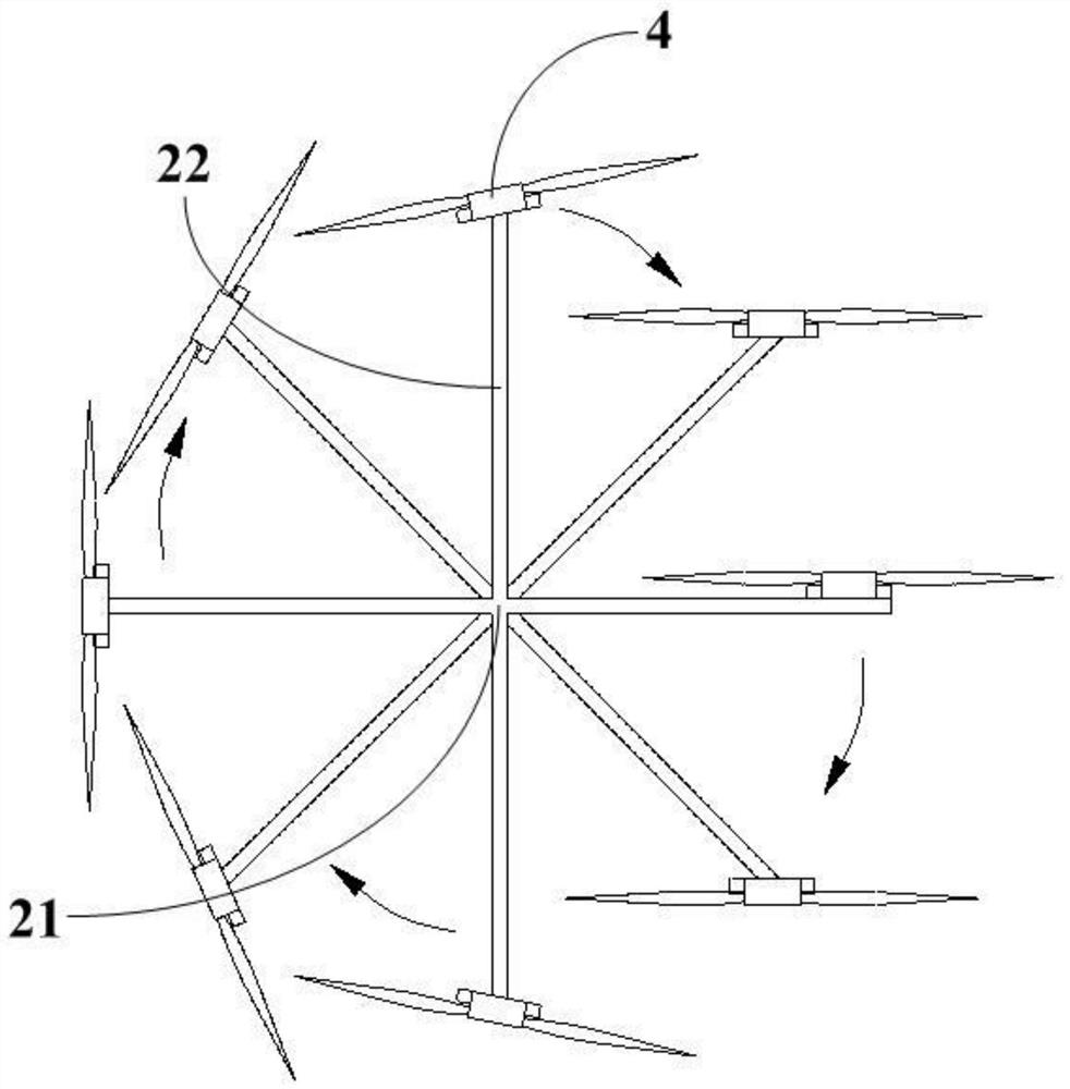
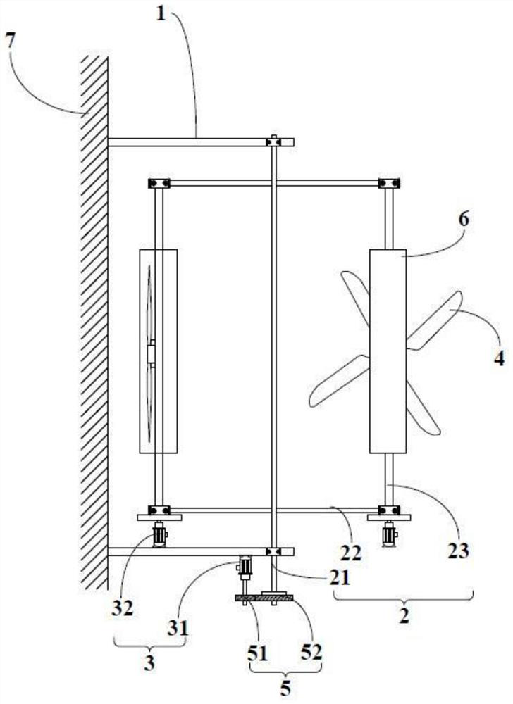
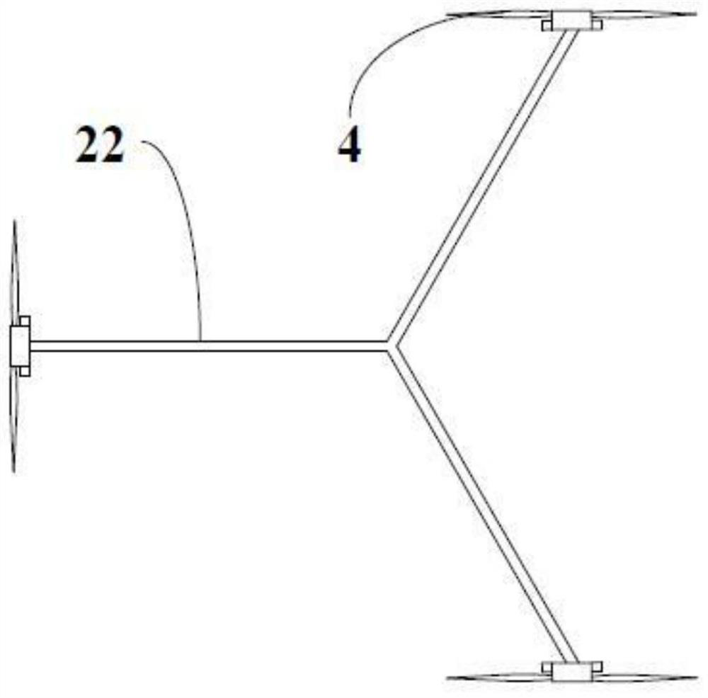
The invention discloses a flapping rotor wing device capable of ascending, half-rotating and descending. Theflapping rotor wing device comprises a supporting assembly, a rotating assembly, a driving assembly and a rotor wing assembly which are in linkage fit. Therefore, the technical effect that an autorotation main shaft of the flapping rotor wing device can autorotate while revolving along witha revolution main shaft is achieved, the rotating surface of the rotor wing assembly can be kept parallel to the horizontal plane all the time in the descending process of the rotor wing assembly, andthen vertically-upward lifting force is provided for an aircraft; the rotor wing assembly can keep the rotating surface of the rotor wing assembly vertical to or approximately vertical to the horizontal plane in the descending process, so that the resistance generated in the ascending process of the rotor wing assembly is reduced, the offset of the lifting force generated in the ascending and descending processes of the rotor wing assembly is avoided, and a continuous and stable lifting force is provided for the take-off and hovering of the aircraft. The flapping rotor wing device is reasonable in design, simple in structure, easy to operate, convenient to control, energy-saving, efficient and good in application prospect.

Description

technical field [0001] The present invention relates to the technical field of aircraft, and more specifically relates to a flapping rotor device with half-rotation upward and downward horizontal operation. Background technique [0002] The flapping-wing aircraft is a flying device designed to imitate the flapping motion of insects or birds. The flapping-wing aircraft mainly relies on the flapping of the blades to generate lift, which can provide a large lift for the aircraft. The flapping-wing aircraft has vertical take-off and landing, hovering, Compared with fixed-wing and rotary-wing aircraft, flapping-wing aircraft has many advantages such as simple structure, light weight, low cost, and high efficiency. If flapping wing flight technology and rotor flight technology can be combined, it will not only have the advantages of vertical lift and hovering in the air that rotorcraft and helicopters have, but also realize that the aircraft consumes less energy during flight, is ...

Claims


Application Information

Patent Timeline
IPC IPC(8): B64C33/02B64C27/32B64C27/22
CPCB64C33/02B64C27/32B64C27/22
Inventor 王志成
Owner GUANGDONG GUOSHIJIAN TECH DEV CO LTD
Learn More