Direct Push Unlocking Locking Mechanism Applied to Intelligent Integrated Feeder Cabinet and Its Feeder Cabinet

A locking mechanism and feeder cabinet technology, applied in the electrical field, can solve the problems of hidden safety hazards for operators, laborious operations, troublesome operations, etc.

Active Publication Date: 2021-07-06
ZHENGZHOU XIANGHE GROUP ELECTRIC EQUIP MFG
View PDF4 Cites 0 Cited by
  • Summary
  • Abstract
  • Description
  • Claims
  • Application Information

AI Technical Summary

Problems solved by technology

[0005] The purpose of the present invention is to provide a direct-push unlocking locking mechanism applied to an intelligent integrated feeder cabinet and its feeder cabinet, which solves the problem of laborious and cumbersome operation when the circuit breaker is connected to the wiring system in the prior art. Relevant operators have great safety hazards and other technical problems

Method used


Image

  • Direct Push Unlocking Locking Mechanism Applied to Intelligent Integrated Feeder Cabinet and Its Feeder Cabinet
  • Direct Push Unlocking Locking Mechanism Applied to Intelligent Integrated Feeder Cabinet and Its Feeder Cabinet
  • Direct Push Unlocking Locking Mechanism Applied to Intelligent Integrated Feeder Cabinet and Its Feeder Cabinet

Examples


Embodiment 1

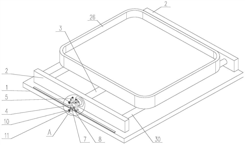
[0053] Such as Figure 1~Figure 11 As shown, the present invention is applied to the direct push unlocking locking mechanism of the intelligent integrated feeder cabinet. A screw 3 that is rotatably connected to a bearing seat 2, wherein,

[0054] One end of the screw rod 3 protrudes from the bearing seat 2 and is coaxially connected with the locking shaft body 4. The cross section of the locking shaft body 4 is non-circular, and a locking assembly is arranged at the end of the locking shaft body 4;

[0055] The locking assembly includes two clamping blocks 5 and a link mechanism and an elastic return mechanism that are both located between the clamping blocks 5 and are not opposite to the end face of the locking shaft body 4 . Both sides of the bottom are slidingly connected with the bottom plate 1, and the sliding direction is perpendicular to the axis of the screw rod 3, and on their opposite sides are provided with a slot 6 that can be fitted with the side wall of the loc...

Embodiment 2

[0063] This embodiment is a further optimization description of the structure in embodiment 1.

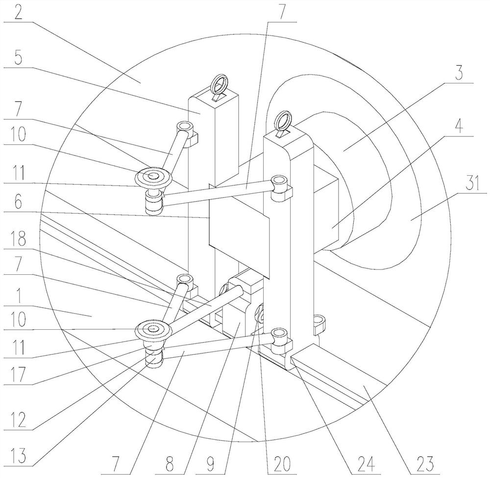
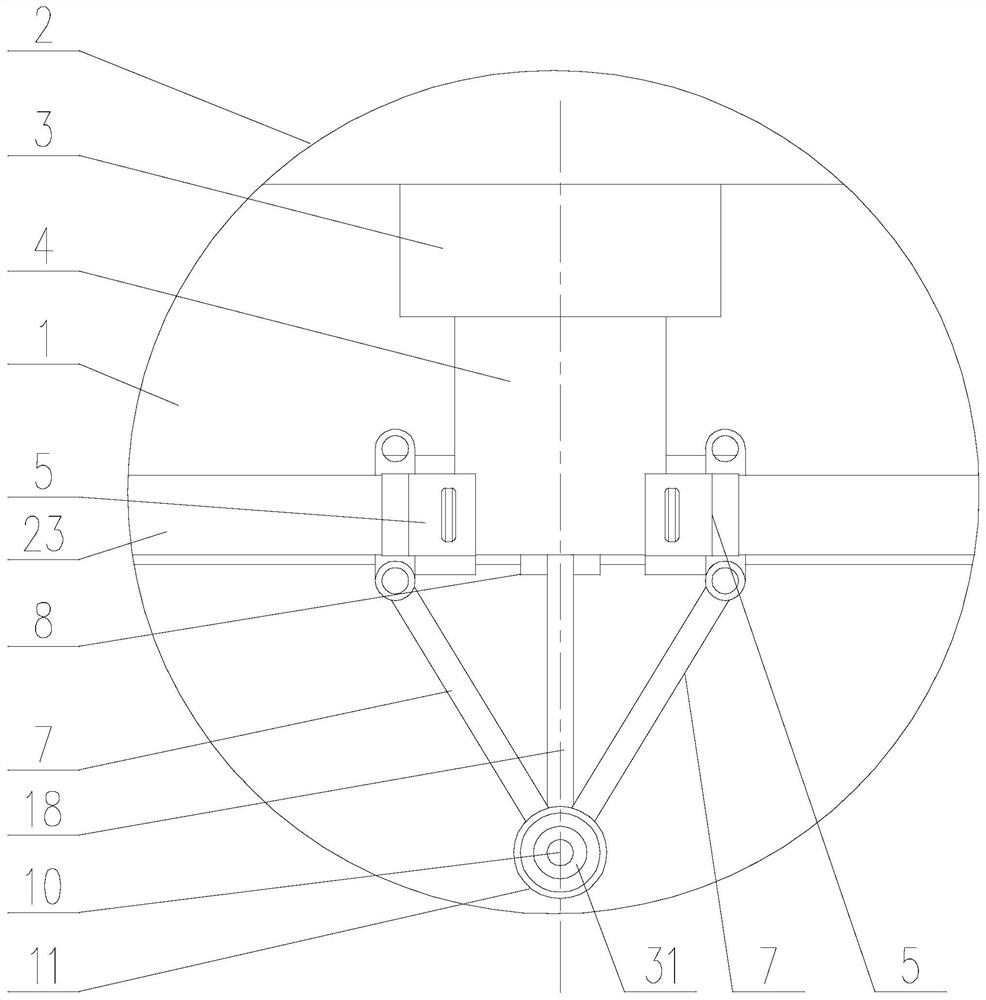
[0064] Such as figure 2 As shown, in the present invention, the linkage mechanism also includes a contact roller 11, and the hinge shaft at one end of the connecting rod 7 is an intermediate hinge shaft 10, and the top end of the intermediate hinge shaft 10 is rotatably connected with a Contact roller 11.

[0065] When the direct push unlocking locking mechanism is applied to the circuit breaker of the feeder cabinet, the circuit breaker is placed above the screw rod, and is driven by the screw rod to move forward and backward along the axis of the screw rod. One end force comes from closing the circuit breaker cabinet door, and the cabinet door rotates around the hinge on one side of its own axis, so the contact part on the cabinet door and the hinged end of the connecting rod 7 will gradually move away and close as the cabinet door closes. One side of the page is offset, that ...

Embodiment 3

[0067] About the structure of one end that connecting rod 7 is hinged mutually is as follows:

[0068] Such as figure 1 , Figure 4 as well as Figure 5 As shown, in the present invention, a first hinged cylinder 12 and a second hinged cylinder 13 are respectively connected to one end of the connecting rod 7 hinged to each other, and an axial dimension and a second hinged cylinder 13 are arranged in the middle of the first hinged cylinder 12 . Two articulated barrels 13 are sockets with matched axial dimensions, the second articulated barrel 13 is inserted into the socket, and the bottom end of the intermediate hinge shaft 10 passes through the upper side of the inner hole of the first articulated barrel 12 and the second articulated barrel in turn. After the 13 inner holes are threadedly connected with the lower side of the first hinge cylinder 12 inner holes;

[0069] An annular groove 14 is arranged on the hole wall of the lower inner hole of the inner hole of the first ...


PUM


Abstract

The invention discloses a direct push unlocking locking mechanism applied to an intelligent integrated feeder cabinet and the feeder cabinet. The feeder cabinet includes a circuit breaker that is slidably installed in the inner cavity of the cabinet through a bearing assembly, fixed on one side of the cabinet through hinges and The circuit breaker cabinet door covered by the inner cavity of the cabinet. The load-bearing component includes a bottom plate, a screw rod and a locking mechanism. One end of the screw rod is connected to the locking shaft body; the locking mechanism includes a locking block, a connecting rod mechanism and an elastic return mechanism. There are card slots; the link mechanism includes two connecting rods, one end of the connecting rods is respectively hinged with a clamping block, and the other ends of the connecting rods are hinged with each other. The rotation of the screw rod is limited by fitting the locking shaft body with the card slot, and the screw rod is locked so that it cannot be rotated, reducing irregular operations, thereby ensuring the safety of workers and preventing damage to related equipment by misoperation; at the same time, through the cabinet door. The electricity is separated from the human body, which improves the safety of the staff's operation, improves the convenience of operation, ensures the simplicity of the structure, and facilitates the maintenance of the present invention.

Description

technical field [0001] The invention relates to the field of electrical technology, in particular to a direct push unlocking locking mechanism applied to an intelligent integrated feeder cabinet and the feeder cabinet thereof. Background technique [0002] The feeder cabinet is also a wiring cabinet. It is a wiring device that distributes the incoming lines of strong or weak current buses to each terminal. [0003] The existing feeder cabinet mainly includes the cabinet body whose inner cavity is the control box installation cavity, the circuit breaker installation cavity and the accessory box installation cavity from top to bottom, the cabinet door fixed on one side of the cabinet body through hinges, and the cabinet body from top to bottom. The control box, circuit breaker and accessory box are installed in the control box installation cavity, circuit breaker installation cavity and accessory box installation cavity in turn. There are three cabinet doors, which are the con...

Claims


Application Information

Patent Timeline
Patent Type & Authority Patents(China)
IPC IPC(8): E05B65/00F16C29/00F16C29/10F16H25/24H02B11/133H02B11/173
CPCE05B65/00F16C29/004F16C29/10F16H25/2454H02B11/133H02B11/173
Inventor 张志伟王国亮裴晓锋巩鲁洪郭慧豪朱峰蔡玉鹏焦俊魏志华罗海李晓亮王凤魏艳春
Owner ZHENGZHOU XIANGHE GROUP ELECTRIC EQUIP MFG
Why Eureka
Try Eureka