Flow path switching valve

A flow path switching and spool technology, applied to multi-way valves, valve devices, valve details, etc., can solve problems such as valve leakage

Pending Publication Date: 2021-02-26
FUJIKOKI MFG CO LTD
View PDF1 Cites 0 Cited by
  • Summary
  • Abstract
  • Description
  • Claims
  • Application Information

AI Technical Summary

Problems solved by technology

Therefore, there is a possibility that a gap is generated between the first slide spool 921 and the first valve seat 913, thereby causing valve leakage.

Method used


Image

  • Flow path switching valve
  • Flow path switching valve
  • Flow path switching valve

Examples


Embodiment Construction

[0030] Below, refer to Figure 1 ~ Figure 4 , the channel switching valve according to one embodiment of the present invention will be described.

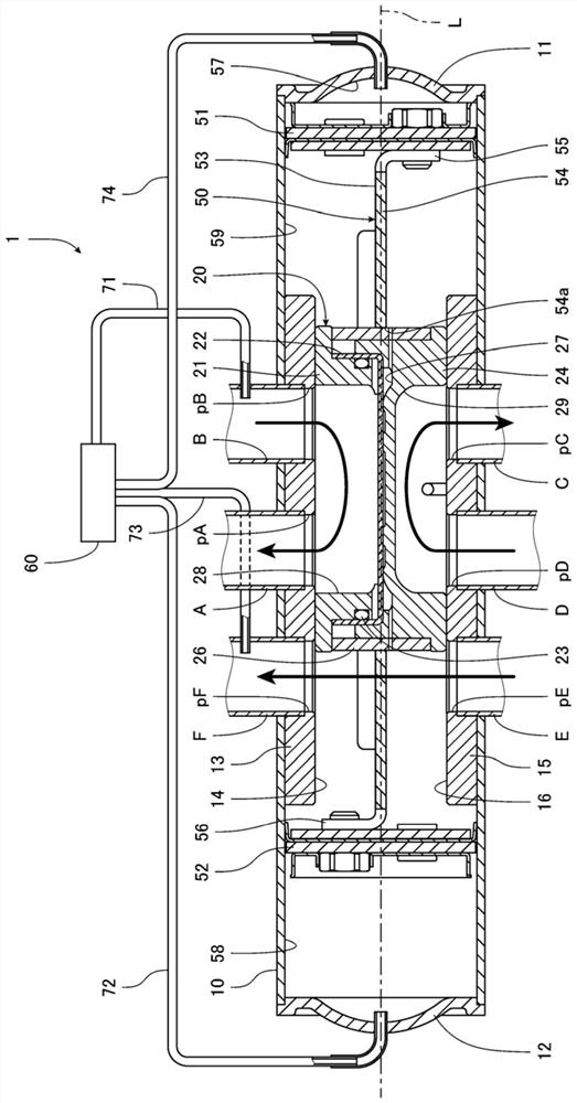
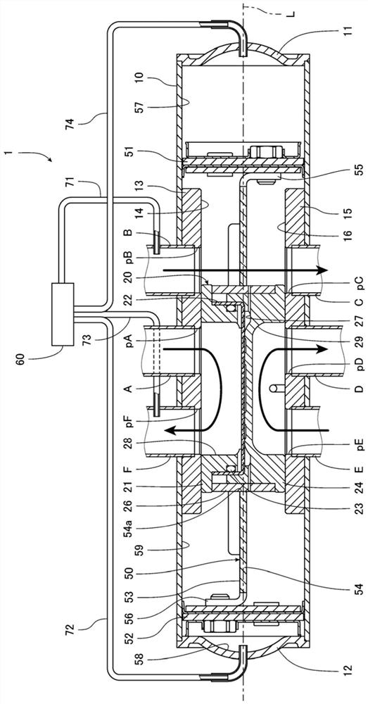
[0031] The flow path switching valve of this embodiment is a six-way switching valve used to switch the flow direction of refrigerant as a fluid in response to switching between cooling and heating operations in heat pump cooling and heating systems such as indoor air conditioners and vehicle air conditioners.

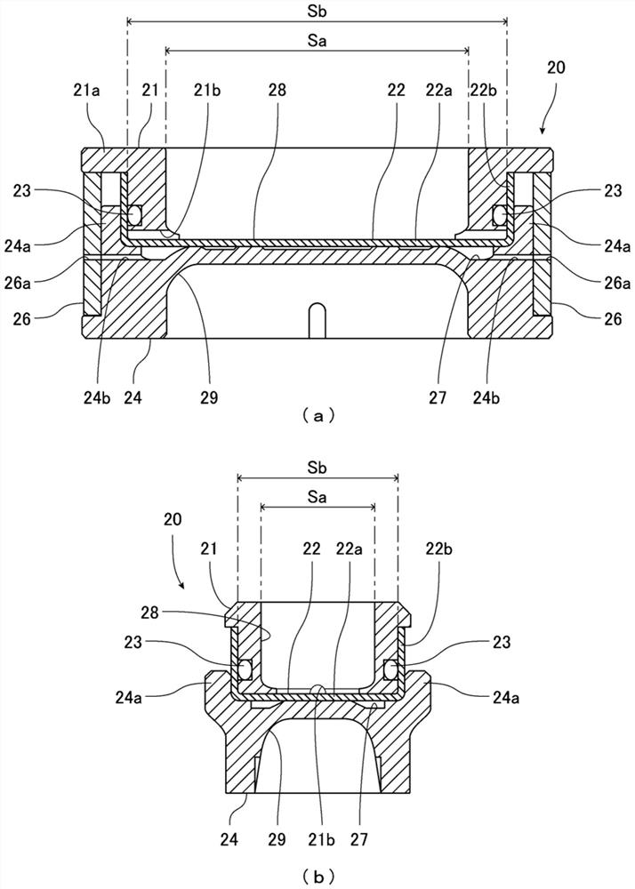
[0032] figure 1 , figure 2 It is a cross-sectional view of a channel switching valve according to an embodiment of the present invention. figure 1 Indicates that the spool is at the first stop position (stop position during cooling operation). figure 2 Indicates the state where the spool is at the second stop position (stop position during heating operation). exist figure 1 , figure 2 In , bold arrows schematically represent examples of fluid flow. image 3 is description figure 1 Diagram of the spool that th...


PUM


Abstract

Provided is a flow path switching valve capable of effectively ensuring a force for pressing a valve body against a valve seat. The flow path switching valve (1) has a first valve seat (13), a secondvalve seat (15), and a valve body (20) disposed in a valve chamber (59) of a valve housing (10). The valve body (20) has a first valve body section (21), a second valve body section (24), and a partition member (22) disposed between the first valve body section and the second valve body section. The partition member is disposed so as to be movable in the direction in which the first valve seat andthe second valve seat face each other with respect to the first valve body section, and closes an opening on the second valve seat side in the first valve body part. The first valve body part and thepartition member are configured so as to form a first U-shaped passage (28). The second valve body section is provided with a second U-shaped passage (29). A back pressure space (27) communicating with the valve chamber (59) is provided between the partition member and the second valve body section.

Description

technical field [0001] The invention relates to a sliding flow path switching valve. Background technique [0002] In heat pump cooling and heating systems such as indoor air conditioners and vehicle air conditioners, a channel switching valve is used that switches the flow direction of refrigerant in accordance with switching between cooling and heating operations. [0003] Patent Document 1 discloses a conventional channel switching valve. Such as Figure 5 As shown, the flow path switching valve 901 is a six-way switching valve, and has a cylindrical valve housing 910 and a spool disposed in the valve housing 910 so as to be slidable in the direction of the axis L by being pressed against a bracket 953 920. A first valve seat 913 and a second valve seat 915 are provided in the valve housing 910 , and the first valve seat 913 and the second valve seat 915 are arranged facing each other in a direction perpendicular to the axis L. As shown in FIG. On the first valve seat ...

Claims


Application Information

Patent Timeline
Patent Type & Authority Applications(China)
IPC IPC(8): F16K11/07F16K27/04F16K31/122F16K47/02
CPCF16K11/0716F16K27/041F16K47/02F16K31/1223
Inventor 后藤聪志木船仁志
Owner FUJIKOKI MFG CO LTD
Why Eureka
Try Eureka