Preconfigured seal for valve assemblies

a valve assembly and preconfigured technology, applied in the field of valve assembly seals, can solve the problems of significant damage to the valve assembly, wear and tear of the mating surface of the valve and the valve seat, and achieve the effect of reducing the velocity reducing the impact force of the valve member, and prolonging the overall life of the valve assembly

Inactive Publication Date: 2013-01-24
S P M FLOW CONTROL
View PDF5 Cites 93 Cited by
  • Summary
  • Abstract
  • Description
  • Claims
  • Application Information

AI Technical Summary

Benefits of technology

[0005]In a first aspect, there is provided a valve assembly including a valve member and a valve seat body. The valve member is reciprocatably movable toward and away from mating engagement with the valve seat body. The assembly further includes at least one deformable seal positioned to be at the situs of engagement of the valve member with the valve seat body. The seal is preconfigured with a recess facing the situs to form a pocket to

Problems solved by technology

Because of the high operating pressures (oftentimes up to 15,000 psi) and the abrasive solid particles associated with the fracturing fluid, the mating surfaces on valves and valve seats tend to wear at a rapid rate, and thus, the valves and valve seats are replaced frequently.
This is principally due to the extremely high fluid pressures creating excessive ax

Method used


Image

  • Preconfigured seal for valve assemblies
  • Preconfigured seal for valve assemblies
  • Preconfigured seal for valve assemblies

Examples


Embodiment Construction

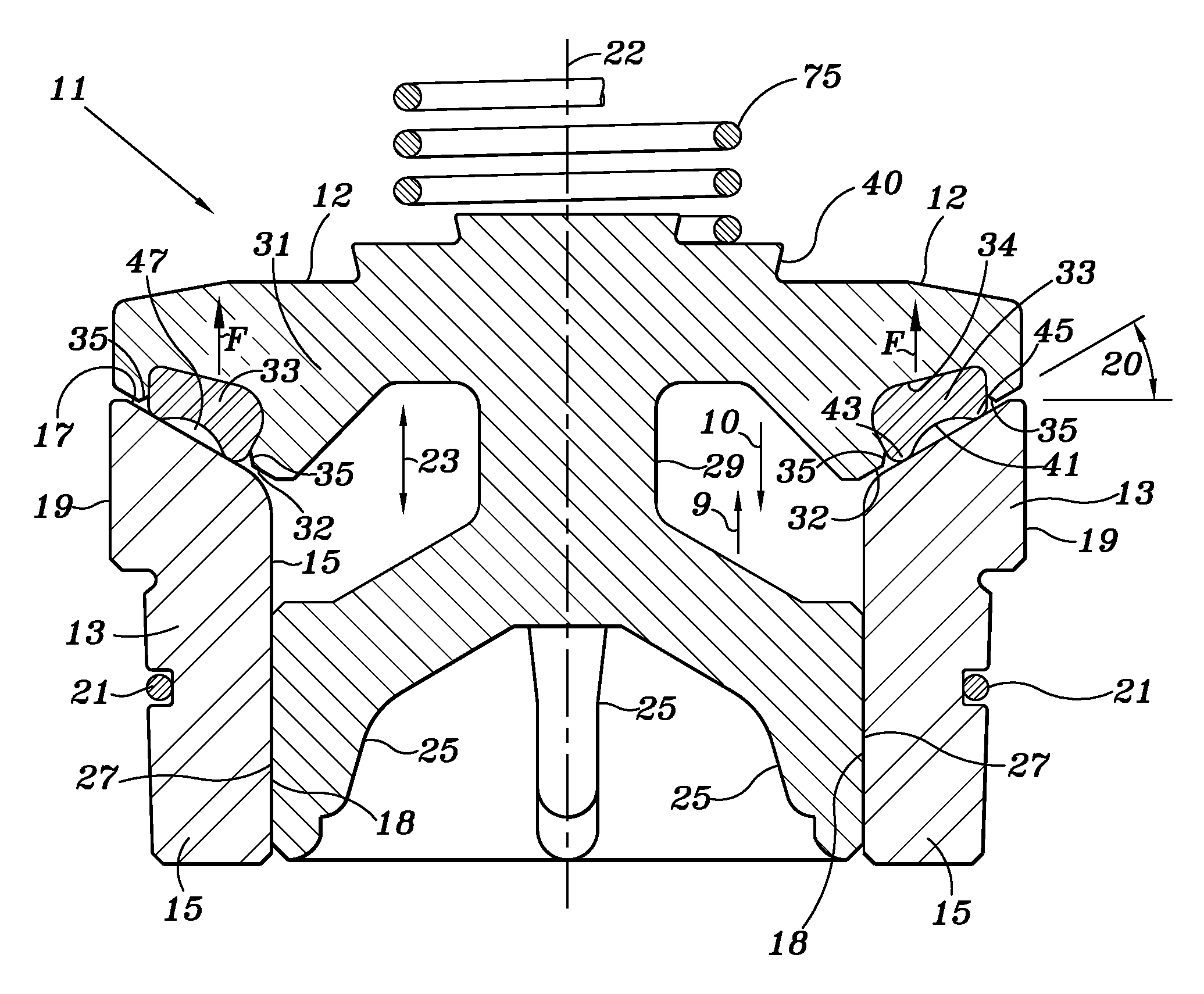
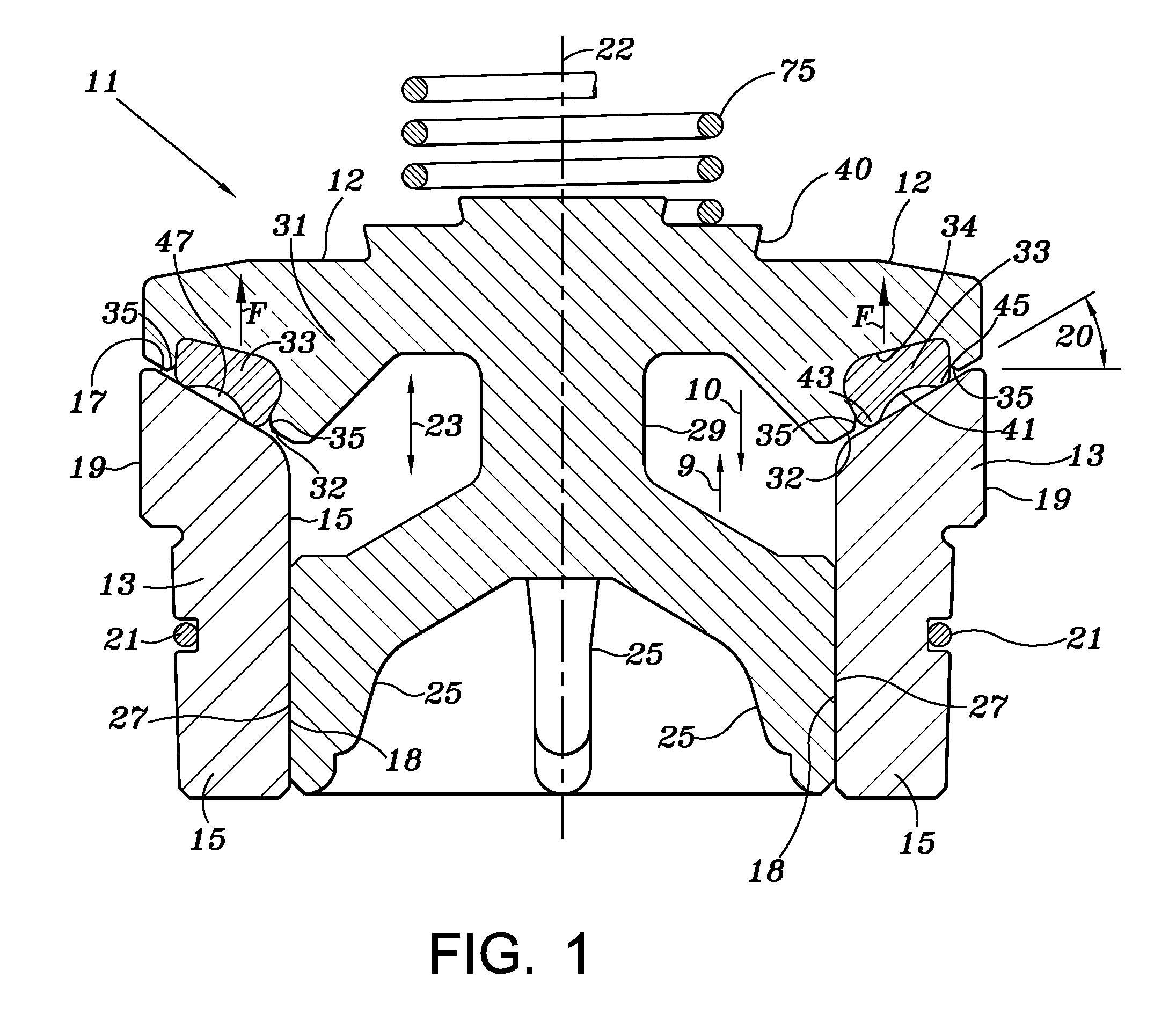
[0040]Referring now to FIG. 1, a valve assembly 11 includes a reciprocatably movable valve member 12 adapted for movement into and out of engagement (as illustrated by arrow 23) with a valve seat body 13. As illustrated in FIG. 1, the valve assembly 11 incorporates at least one deformable seal 33 positioned at the situs of engagement between the valve member 12 and the valve seat body 13 such that, as explained in greater detail below, the seal 33 forms a pocket 47 to trap fluid therein as valve member 12 approaches the engagement to otherwise seat against the valve seat body 13 in a closed position. By trapping fluid within the pocket 47, pressure therein is increased thereby creating a force F acting opposite to a valve closing force such that when the valve assembly 11 reaches the closed position, the axial load on the valve member 12 and the valve seat body 13 is reduced. Furthermore, the seal 33 and the pocket 47 are positioned and otherwise formed to reduce the velocity of the...


PUM

PropertyMeasurementUnit
Angleaaaaaaaaaa
Angleaaaaaaaaaa
Velocityaaaaaaaaaa

Abstract

A valve assembly is disclosed herein having a valve member and a valve seat body. The valve member is reciprocatingly movable into and out of engagement with the valve seat body. The assembly further includes at least one deformable seal positioned to be at the situs of engagement of the valve member with the valve seat body. The at least one seal is preconfigured with a recess facing the situs to form a pocket to trap fluid therein as the valve member approaches the engagement, which reduces the velocity of the valve member moving toward the engagement and reduces the impact force of the valve member on the valve seat body. Furthermore, the fluid disposed within the pocket also reduces the axial load on the valve member and valve seat body.

Description

CROSS-REFERENCE TO RELATED APPLICATIONS[0001]This application claims priority to U.S. Provisional Patent Application Ser. No. 61 / 475,418, filed on Apr. 14, 2011, which is incorporated herein by reference in its entirety.TECHNICAL FIELD[0002]This disclosure relates in general to valve assembly seals, more particularly to valve assemblies incorporating uniquely preconfigured seals, and even more particularly to valve assemblies as incorporated with reciprocating pumps.BACKGROUND OF THE DISCLOSURE[0003]Large pumps are commonly used for mining and oilfield applications, such as, for example, hydraulic fracturing. During hydraulic fracturing, fracturing fluid (i.e., cement, mud, frac sand and other material) is pumped at high pressures into a wellbore to cause the producing formation to fracture. One commonly used pump in hydraulic fracturing is a high pressure reciprocating pump, like the SPM® Destiny™ TWS 2500 frac pump, manufactured by S.P.M. Flow Control, Inc. of Fort Worth, Tex. Acc...

Claims


Application Information

Patent Timeline
IPC IPC(8): F16K1/00B21K1/24
CPCF16K1/385Y10T29/49409F16K15/063F16K1/44
Inventor BYRNE, JOSEPH H.
Owner S P M FLOW CONTROL
Why Eureka
Try Eureka