Docking stations for transcatheter valves

a transcatheter valve and station technology, applied in the field of docking stations for transcatheter valves, can solve the problems of serious cardiovascular compromise or death, inability to secure the aortic transcatheter valve into the larger implantation or deployment site, and the effect of less effective heart valves

Active Publication Date: 2019-01-03
EDWARDS LIFESCIENCES CORP
View PDF0 Cites 92 Cited by
  • Summary
  • Abstract
  • Description
  • Claims
  • Application Information

AI Technical Summary

Benefits of technology

[0034]The docking station can include at least one leg that extends proximally at a proximal end of the docking station and is releasably connectable to the retention device. The docking station can include multiple legs that extends proximally at a proximal end of the docking station, and the multiple legs can be spaced evenly radially around the proximal end of the docking station. The docking station includes only one leg that extends proximally at a proximal end of the docking station and is releasably connectable to the retention device, such that the docking station can fully expand while the one leg is connected to the retention device and then be released.

Problems solved by technology

These heart valves can be rendered less effective by congenital, inflammatory, infectious conditions, etc.
Such conditions can eventually lead to serious cardiovascular compromise or death.
However, with larger native valves, blood vessels (e.g., an enlarged aorta), grafts, etc., aortic transcatheter valves might be too small to secure into the larger implantation or deployment site.
In this case, the transcatheter valve may not be large enough to sufficiently expand inside the native valve or other implantation or deployment site or the implantation / deployment site may not provide a good seat for the THV to be secured in place.
As one example, aortic insufficiency can be associated with difficulty securely implanting a THV in the aorta and / or aortic valve.

Method used


Image

  • Docking stations for transcatheter valves
  • Docking stations for transcatheter valves
  • Docking stations for transcatheter valves

Examples


Embodiment Construction

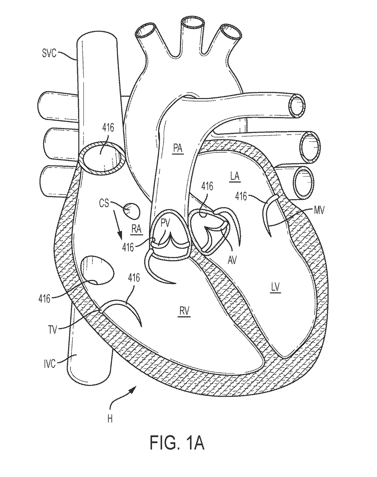
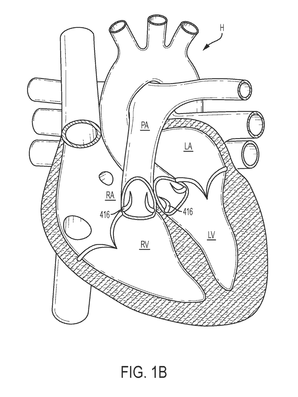
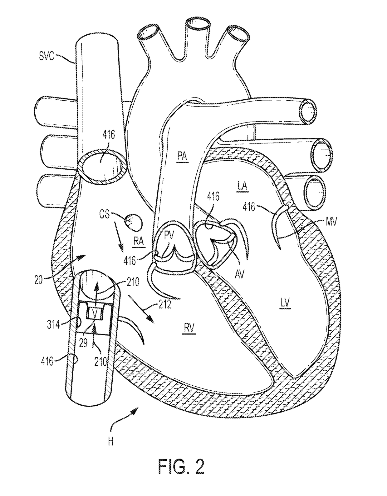
[0148]The following description refers to the accompanying drawings, which illustrate specific embodiments of the invention. Other embodiments having different structures and operation do not depart from the scope of the present invention. Exemplary embodiments of the present disclosure are directed to devices and methods for providing a docking station / device or landing zone for a prosthetic valve (e.g., a transcatheter valve, such as a transcatheter heart valve), e.g., valve 29. In some exemplary embodiments, docking stations / devices for prosthetic valves or THVs are illustrated as being used within the superior vena cava (SVC), inferior vena cava (IVC), or both the SVC and the IVC, although the docking stations / devices (e.g., docking station / device 10, other docking stations / devices herein, modified versions of the docking stations, etc.) can be used in other areas of the anatomy, heart, or vasculature, such as the tricuspid valve, the pulmonary valve, the pulmonary artery, the a...


PUM


Abstract

Docking stations for transcatheter valves are described. The docking stations can include an expandable frame, at least one sealing portion, and a valve seat. The expandable frame can be configured to conform to an interior shape of a portion of the circulatory system when expanded inside the circulatory system. The sealing portion can be configured to contact an interior surface of the circulatory system to create a seal. The valve seat can be connected to the expandable frame and can be configured to support an expandable transcatheter valve. The docking stations are adaptable to different anatomies/locations to allow implantation of a transcatheter valve in a variety of anatomies/locations.

Description

CROSS-REFERENCE[0001]The present application is a continuation of U.S. International Application No. PCT / US2018 / 040425 filed Jun. 29, 2018, which claims priority to U.S. Provisional Patent Application No. 62 / 527,577, filed Jun. 30, 2017, U.S. Provisional Patent Application No. 62 / 529,996, filed Jul. 7, 2017, and U.S. Provisional Patent Application No. 62 / 529,902, filed Jul. 7, 2017. The entire disclosures of the foregoing are incorporated herein by reference in their entirety.BACKGROUND OF THE INVENTION[0002]Prosthetic heart valves can be used to treat cardiac valvular disorders. The native heart valves (the aortic, pulmonary, tricuspid and mitral valves) function to prevent backward flow or regurgitation, while allowing forward flow. These heart valves can be rendered less effective by congenital, inflammatory, infectious conditions, etc. Such conditions can eventually lead to serious cardiovascular compromise or death. For many years, the doctors attempted to treat such disorders ...

Claims


Application Information

Patent Timeline
Patent Type & Authority Applications(United States)
IPC IPC(8): A61F2/24
CPCA61F2/2418A61F2/2436A61F2/2433A61F2220/005A61F2220/0075A61F2220/0016A61F2/90A61F2/2409A61F2/2412A61F2/2475A61F2220/0025A61F2220/0091A61F2002/9534A61F2250/0063A61F2/9522A61F2/07A61F2002/061A61F2/88A61F2230/005A61F2230/0054A61F2250/0039
Inventor TAYEB, LIRONGOLDBERG, ERANMAIMON, DAVIDCARMI, ADITYLIS, ARIEWITZMAN, OFIRSCHNEIDERJAFARI, MOHAMMADCAO, HENGCHUABBOTT, EASON MICHAELARMER, DUSTIN P.FRANKLIN, MICHAEL D.SAAR, TOMERDVORSKY, ANATOLYDESROSIERS, JOHN J.MURRAY, DANIEL JAMESVALDEZ, MICHAEL G.BASH, ASSAFBLUMENFELD, AMIRAXELROD, NOAATIAS, EITAN
Owner EDWARDS LIFESCIENCES CORP
Why Eureka
Try Eureka